====== Communication between Mervis IDE and Jablotron 100 ======
Do you own or are going to integrate the Jablotron 100 electronic security system (ESS) and you want to use the electronic security system peripherals and sections for other different purposes?
Data from the security system can be easily used for energy savings as well as other ideas. The following tutorial will guide you through both the HW and SW setup of the Jablotron 100 and Mervis IDE.
;;#
Patron \\
Neuron \\
Gate \\
Unipi 1.1 \\
Axon
;;#
Prerequisites:
* Unipi controller running [[en:files:software:os-images:00-start|Mervis OS v2.3.0]] or higher
* [[https://www.unipi.technology/en/accessories-c4|24 V⎓ power supply]]
* local network connectivity (any switch or router)
* Jablotron 100(+) ESS control panel
* Jablotron JA-121T, RS-485 module
* [[https://www.unipi.technology/en/accessories-c4|6-28 V⎓ power supply]] for the JA-121T module
===== 1 Connection of the JA-121T module =====
The JA-121T module provides galvanic isolation of Jablotron100 and RS-485 lines, using the separate power supply for each side highly recommended. One side of the module is powered by the Control Module. For the **galvanically isolated** side, use a 6-28 V⎓ power supply different to the one used for PLC (see the module’s user manual). Connect the **D+** terminal on JA-121T with the **RS485-A** terminal on the PLC. Repeat for the **D-** and **RS485-B** terminals.
{{ :en:sw:01-mervis:Jablotron100_en_01.png?nolink |}}
===== 2 Description and configuration of the Control Module =====
==== 2.1 Introduction ====
Jablotron 100(+) ESS Control Modules and their peripherals communicate via proprietary Jablotron bus. The JA-121T module acts as a gateway, converting the internal Jablotron bus to RS-485 serial bus with ASCII communication and providing information about the ESS to other systems. The module allows the user to set or read states of peripherals, sections or PGs.
=== 2.1.1 Section ===
Using **Section_state** data points, it is possible to read or change states of the individual sections (armed, disarmed, maintenance etc.). **Section_flag** datapoints then display states of sirens, types of alarms, or enter and exit delays.
=== 2.1.2 PG ===
Regarding Jablotron Control Modules, PGs are variables that can be controlled by various states, peripherals etc. In some installations, physical inputs or outputs can be also mapped to PGs. PGs are especially suitable for this tutorial due to their very short response time. PG can, for example, represent peripheral status, allowing you to read it from the system much faster.
=== 2.1.3 Periferie ===
The term "peripheral" encompasses various external devices such as window magnetic contacts, motion sensors, camera traps etc. Unfortunately, the JA-121T module refreshes the current peripheral states every 10 seconds – this delay makes it unsuitable for some applications as peripheral states may not be always reliably detected. If you need faster read time, you can opt for reading PGs instead.
=== 2.1.4 JA-121T modes - Active vs Passive ===
== Active ==
In this mode, the JA-121T module communicates spontaneously. Each time a change is detected on a section, PG or peripheral*, the module responds by sending a message about the change. This mode is not suitable for installations requiring writing data into the Control Module, as it would result in collisions on the RS-485 line between the module and the PLC.
//*Peripheral states are updated once per 10 seconds.//
== Passive ==
Passive mode is based on a query/response model. It is necessary to use passive mode if your installation requires the PLC to set anything in the ESS(section settings, PG controls etc.).
==== 2.2 Configuration of Control Module ====
Update the Control Module (including peripherals) before the first connection to the PLC.
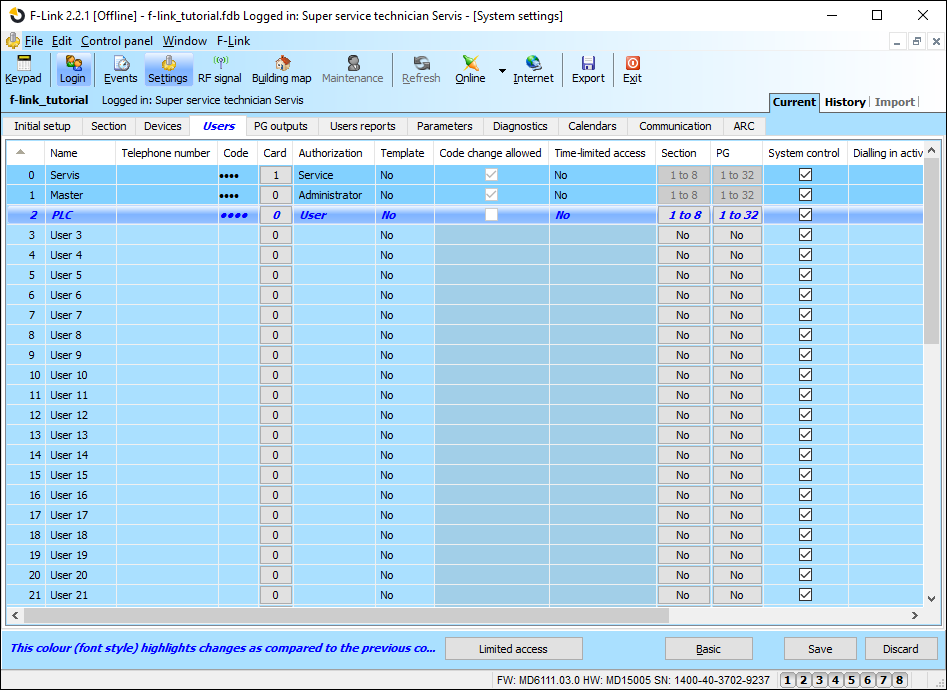
**For writing into the ESS:** Create an independent user for the PLC in the Control Module and grant it all necessary privileges, a prefix (first column) and a code (fourth column). The Mervis IDE will require these credentials for configuration of the Jablotron 100 communication protocol.
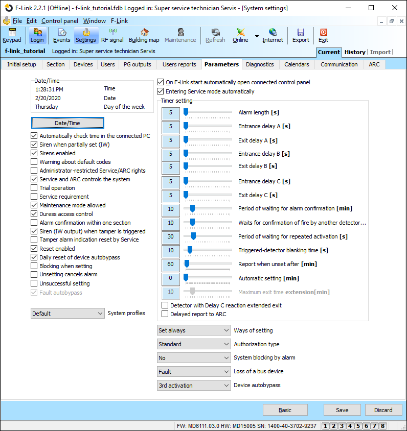
In the Control Module settings, configure the JA-121T module as following:
* Device basic mode – Terminal console
* TMP terminal – based on the module’s placement (set by ESS technician)
* Motherboard button – set by ESS technician
* Period after which a fault is triggered – 0
* Connection confirmed – Disabled
* Passive mode – set by checking the option, otherwise the active mode is used (see [[#ja-121t_modes_-_active_vs_passive|Chapter 2.1.4]])
{{ :en:sw:01-mervis:Jablotron100_en_03.png?nolink |}}
If you want for the PLC to notice Control Module sabotage even if the ESS is not armed, check the „Siren when tamper is triggered“ option checkbox.
**__Important data from the Control Module required by Mervis IDE__**
**Control Module mapping:**
* description and position of each peripheral, section, or description of the function of the individual PGs
**For writing into the ESS:**
* prefix + user password
* list of sections and PGs the user can control
===== 3 Mervis IDE settings =====
This chapter is divided into three parts. The first part focuses on adding a reference to the Lib.Jablotron library, which is necessary for using prepared Jablotron Control Modules in Mervis IDE. The second part contains a description of setting up the Control Module’s communication channel and the module itself. The last part deals with the configuration of the device added in the second chapter – this configuration is performed to optimize the communication.
Now create a new Mervis IDE project or open an already existing project. Follow the steps listed below:
==== 3.1 Přidání reference na knihovnu Lib.Jablotron ====
The Lib.Jablotron library simplifies the Jablotron module management by using predefined function blocks and transformations. The reference must be added before using the **SectionTransform** transformation in the project, as these transformations are used directly in the prepared Control Module devices.
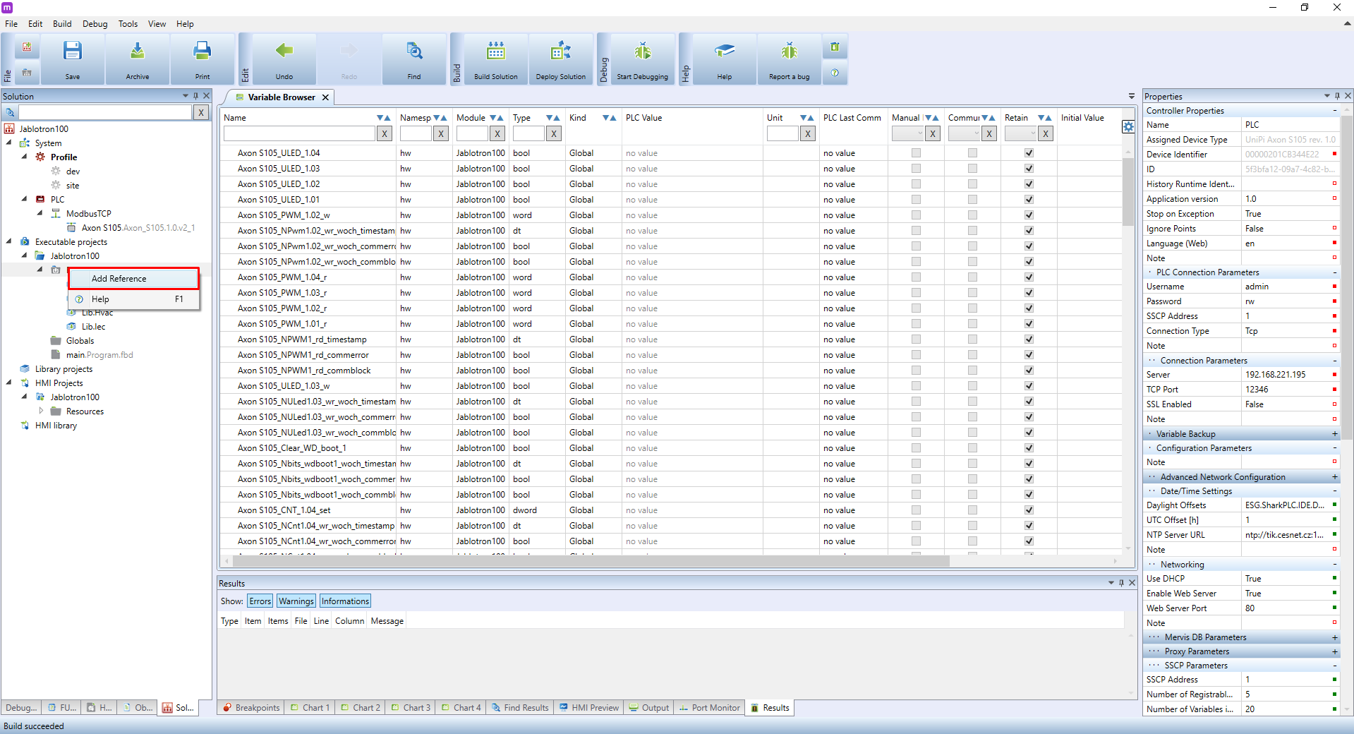
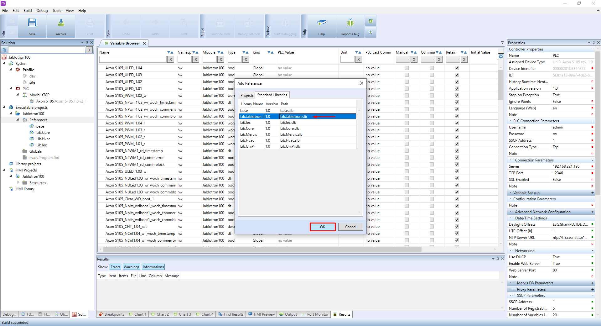
You can add the reference by right-clicking on **Reference** and selecting **Add Reference**.
Then click on **Standard libraries**, select the required library, and confirm by **OK**.
==== 3.2 Adding a communication channel in Mervis IDE and attachment of Control Module ====
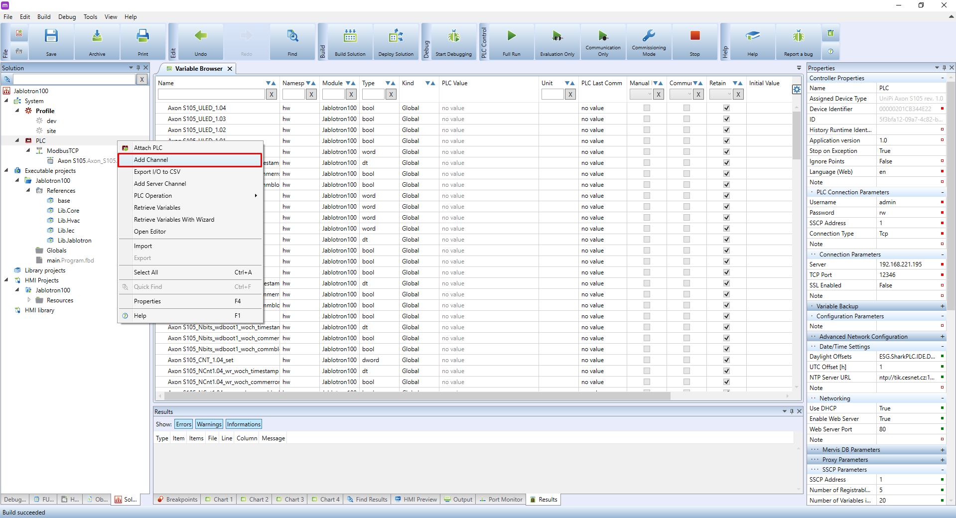
Create a new channel by right-clicking on the PLC’s and selecting **Add Channel**.
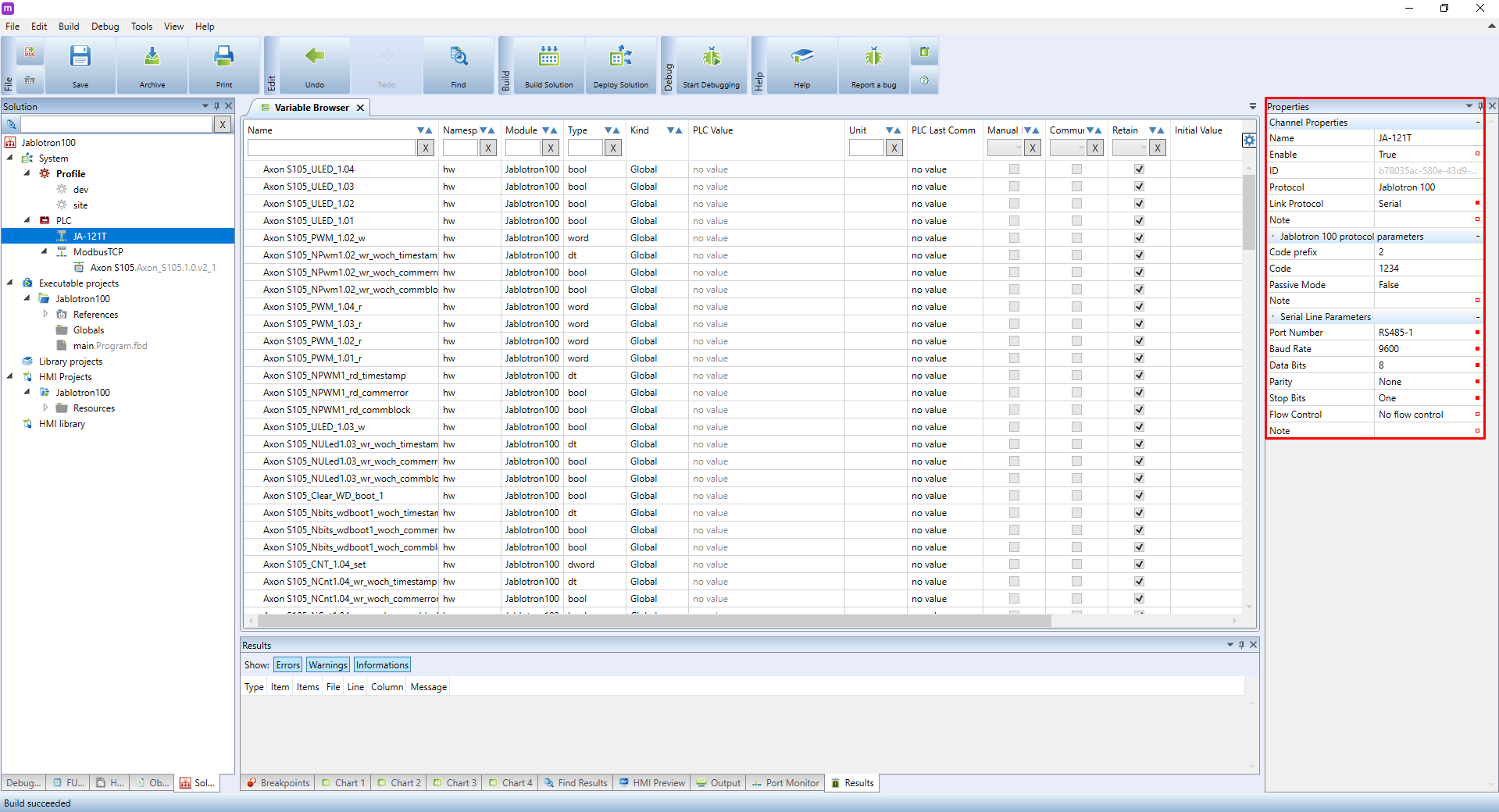
Click on the newly added channel and move into its **Properties** in the **right panel**. Set its properties to the following:
Channel properties \\
**Name** – use something descriptive like JA-121T or Jablotron 100 \\
**Enable** – set to TRUE to enable the channel \\
**Protocol** – select "Jablotron 100" \\
**Link protocol** – select "Serial"
Jablotron 100 protocol parameters \\
**Code prefix** – fill in only when writing to the Control Module, represents a user number created in Control Module settings (ie. service technician – 0) \\
**Code** – fill in only when writing to the Control Module – access code of the user \\
**Passive mode** – set to TRUE if you want to write into the control module, otherwise **FALSE** (must correspond with the ESS settings), described in [[#ja-121t_modes_-_active_vs_passive|chapter 2.1.4]]
Serial Line Parameters \\
**Port Number** – select the RS-485 port to which the JA-121T module is connected \\
**Baud Rate** – set to __9600__ baud \\
**Data Bits** – set to __8__ \\
**Parity** – set to "__None__" \\
**Stop Bits** – set to "__One__"
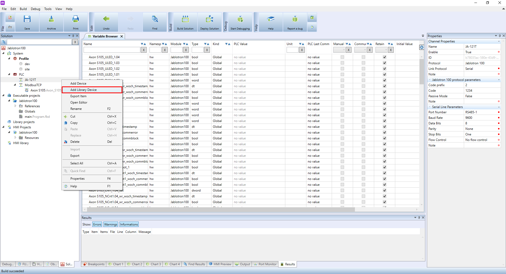
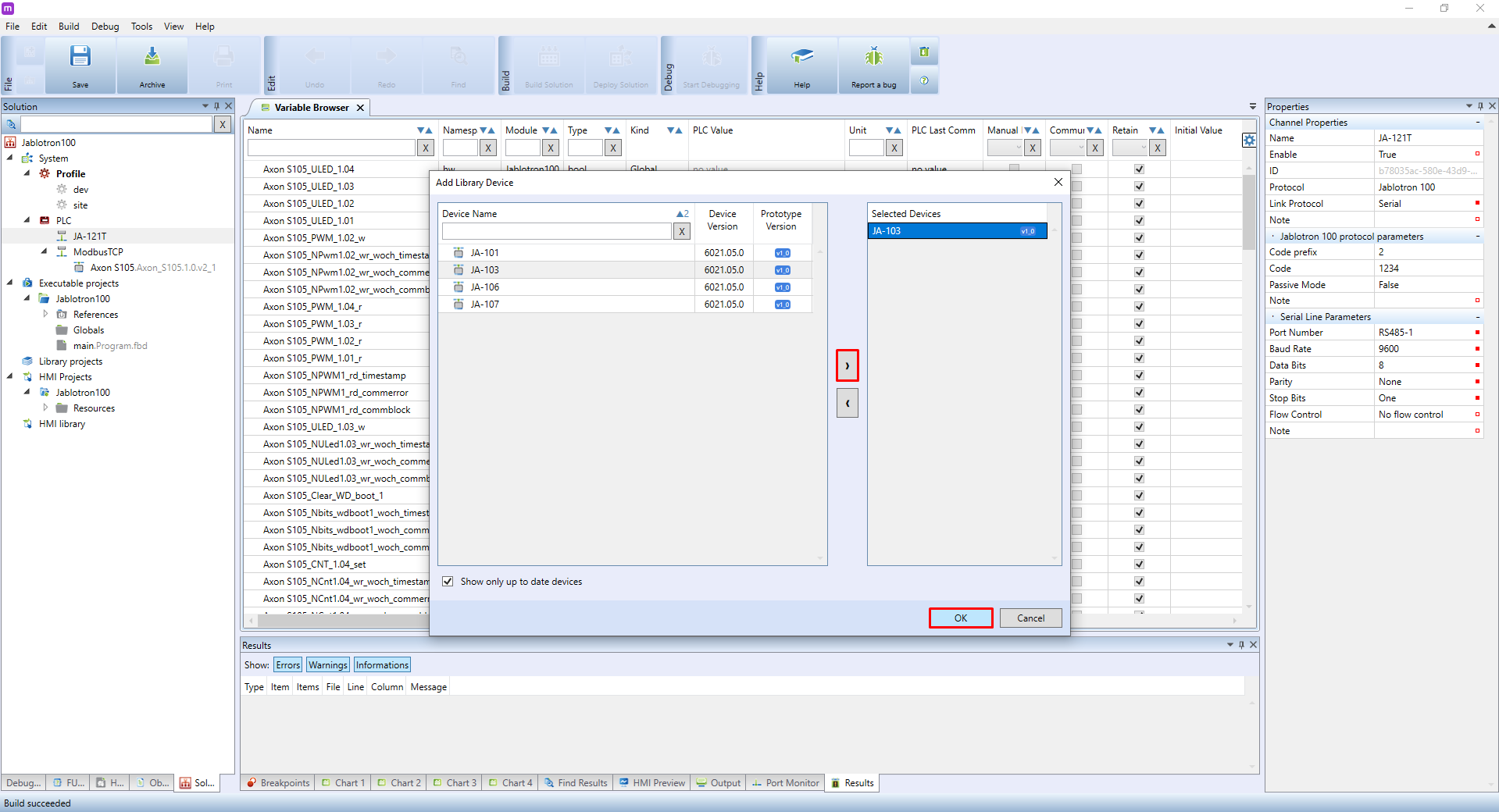
Upon finishing the configuration, right-click on the channel’s name to display a context menu. Click on **Add Library Device**.
Mervis IDE contains a predefined all available Control Module devices with all of the sections, peripherals, and PG for each Control Module type, including writing data points or input-output data point couples. A dialogue will appear. Select the required type of Control Module. Confirm by clicking on **OK**.
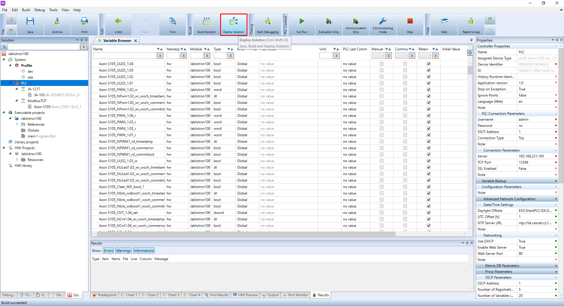
The device is now ready. You can deploy the solution into the PLC.
The newly added device contains all available Control Module configurations. To ensure proper functionality, however, you need to optimize the device first, eg. to remove all data points of unused sections, peripherals, or PGs.
==== 3.3 Optimization of Control Module device in Mervis IDE ====
If you use the Control Module in the active mode, you can skip this chapter and proceed to [[#example_of_using_function_blocks_and_enumerated_types|Chapter 4]].
ESS values are read by groups. Each group has its own data read interval – 2 seconds for library devices, 5 seconds for peripherals and 5 milliseconds for PGs. This configuration is designed to ensure communication stability and to decrease data read delays as much as possible.
The optimization will be described in a practical installation example.
=== 1 Example setup: ===
You want the PLC to read from the JA-103 Control Module two sections – Section 1 and Section 2. You also need to monitor 5 sensors mapped to the first five PGs of the Control Module. PG state is read from the Control Modules in 1–1.5 s. The JA-121T module must be set to **passive** mode. Reading from ESS is dependent on traffic on the bus.
=== 2 Optimization guide: ===
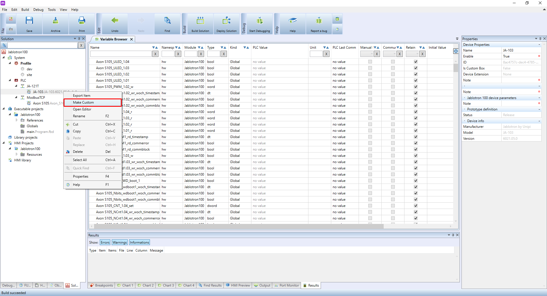
Right-click on a device on the **JA-121T** channel and click **Make Custom** to enable device modifications.
If you have to switch the Mervis IDE project into the **Full mode**, it is necessary to set **Autogen** for the entire **JA-103.generic** device.
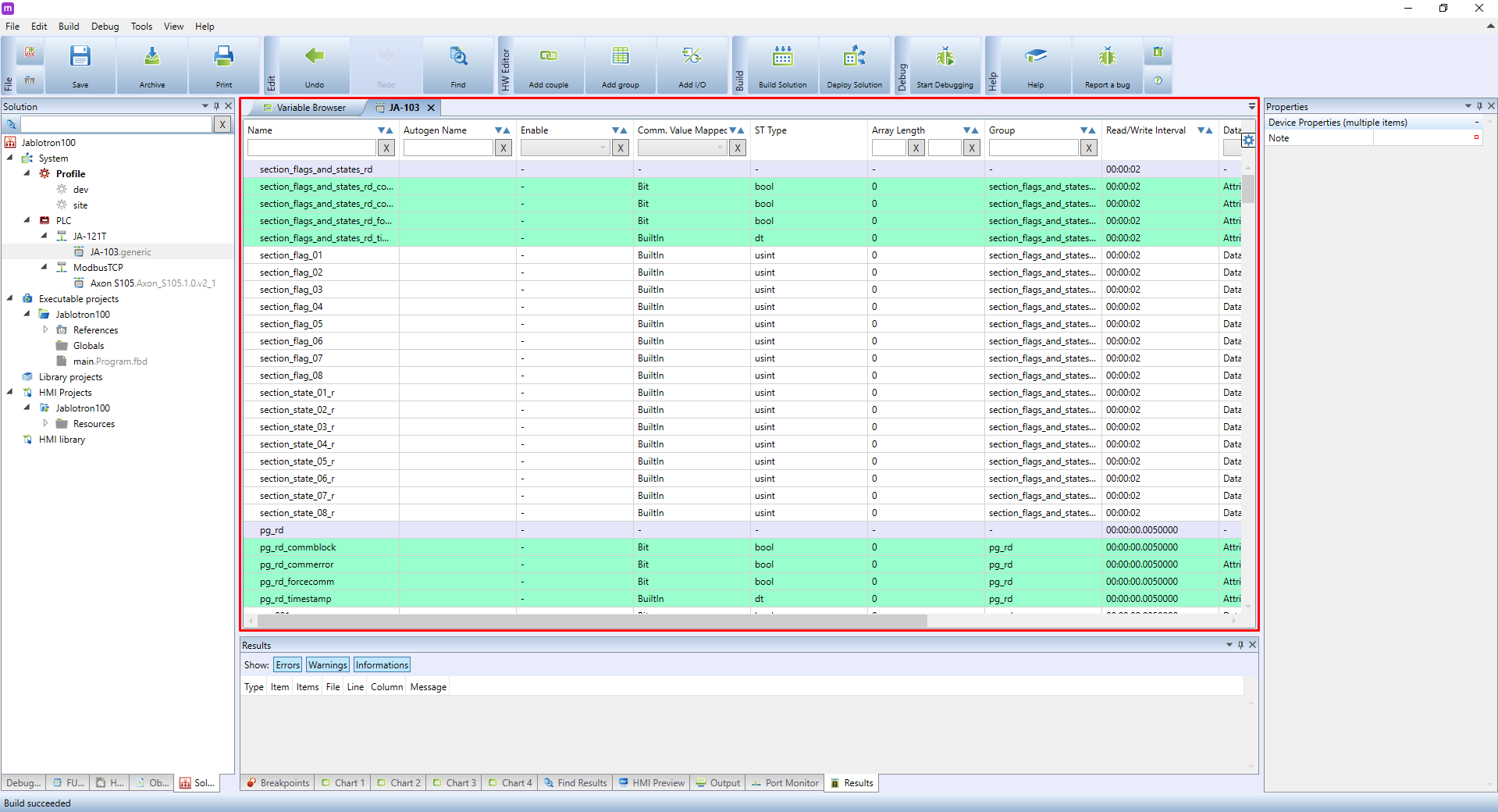
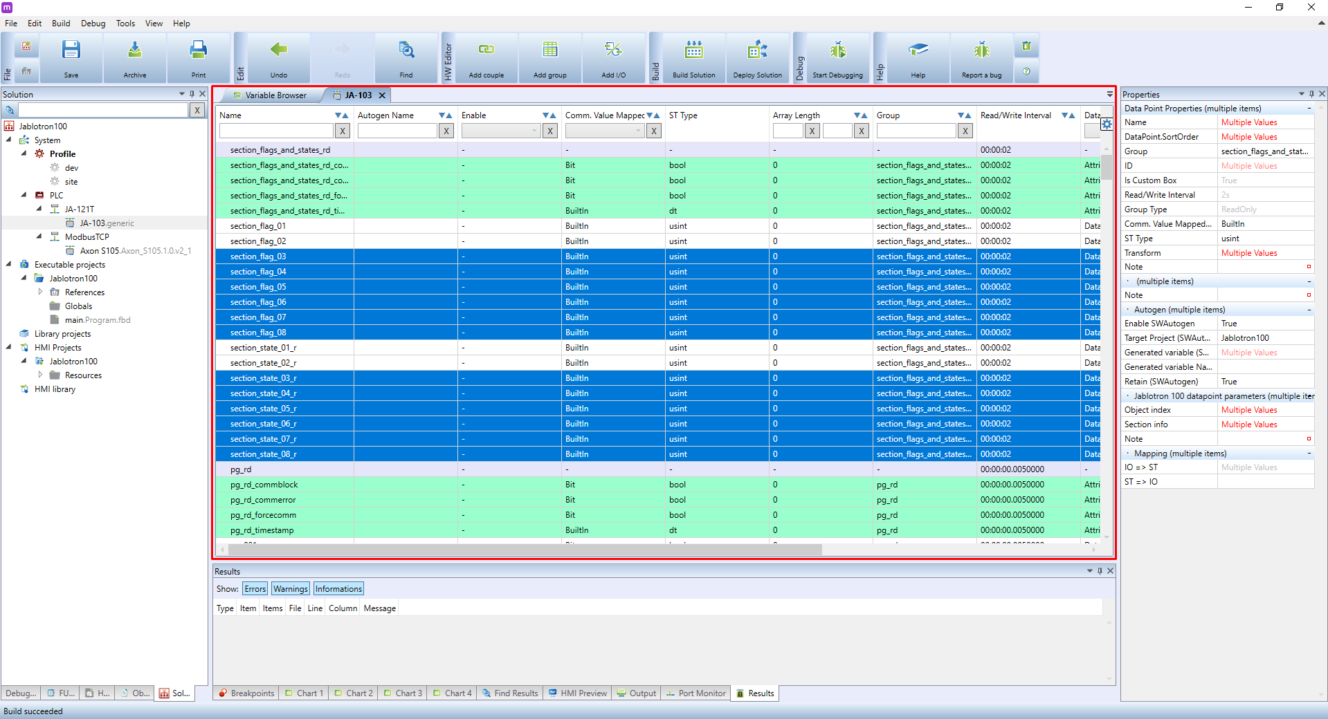
Double-click on the JA-103.generic device to display a list of communication groups and data points of all individual peripherals, PGs, or sections with their flags.
To ease up orientation, Groups and their States have purple and green background while Data points have a white background.
\\
The peripheral reading interval is set to 5 seconds by default which provides the fastest possible reading. The reason for this is that the JA121-T module updates peripheral states once every 10seconds. If a faster response is needed, you need to use PGs which represent states of peripherals. PGs can be used to map states of peripherals as well as other parts of the ESS. The Control Module thus must be configured for copying states of the selected peripherals (or sensors) to the Control Module’s PGs. The time to update the state of a PG depends on the total number of PG, sections and other things that are communicated. The communication will be slightly slowed also by peripheral reading – this reading depends only on whether the peripherals are read or not.
\\
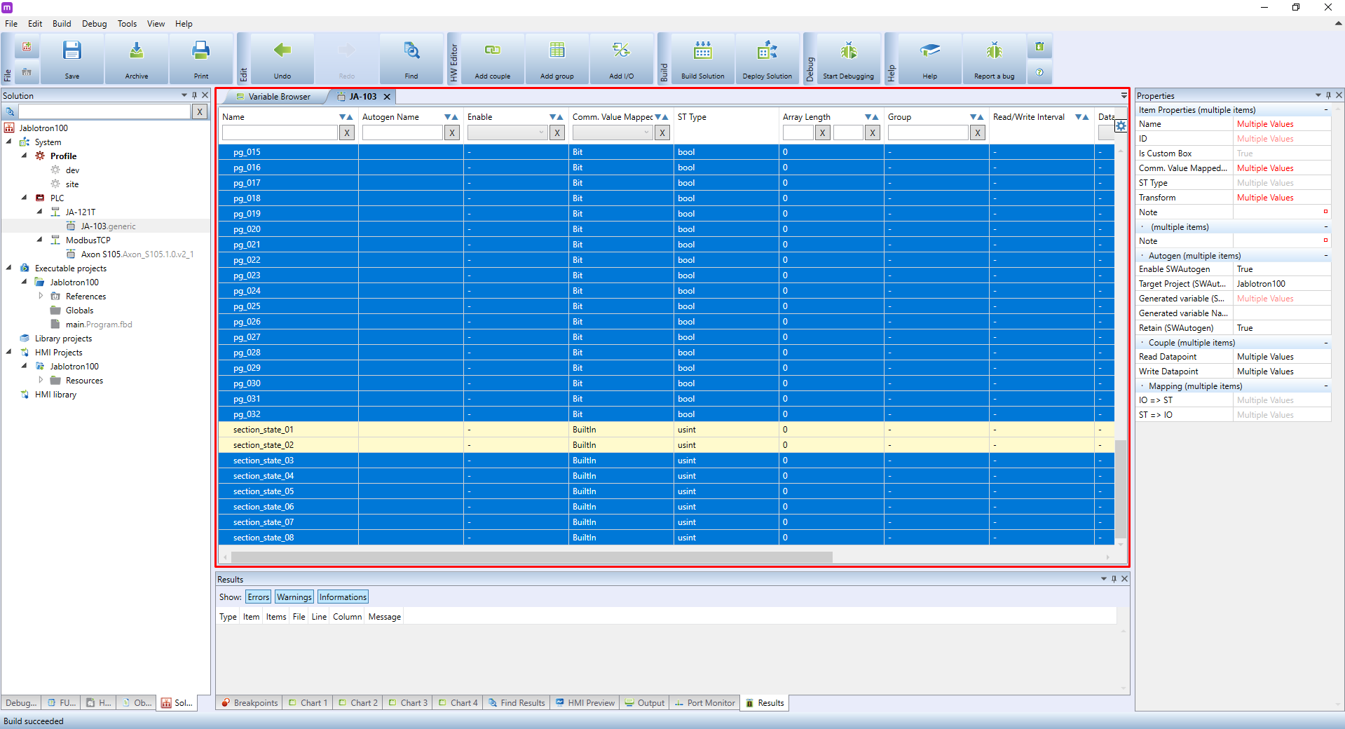
Select all unused sections and flags which will not be used. These are data points beginning with **section_flag** and **section_state** which are part of **section_flags_and_states_rd** group. For this tutorial, select sections 3-8 and their flags, and remove them by pressing the **DELETE** key.
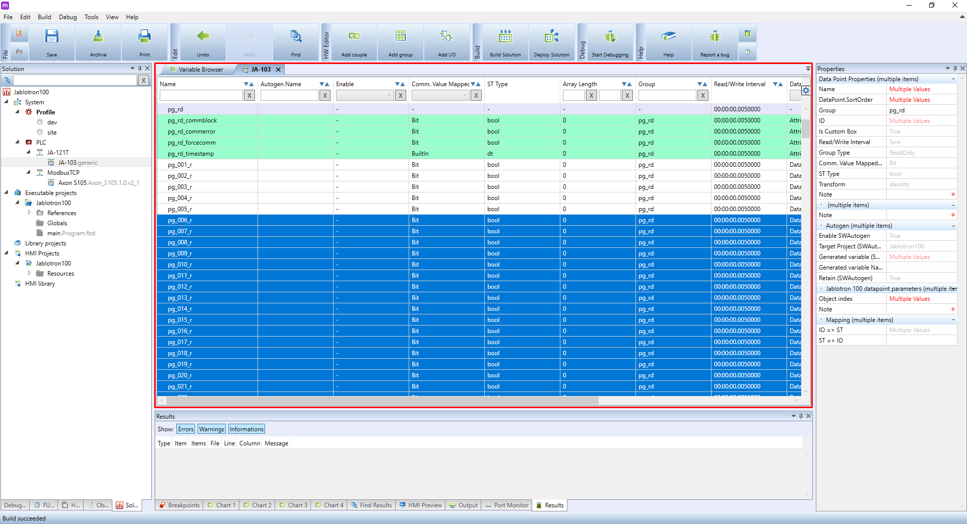
Repeat the same procedure for reading states of PGs, in particular data points of group **pg_rd** beginning with **pg_**. In our tutorial, we need to monitor 5 sensors mapped to PGs 1-5, so we delete the PGs 6-32 that are no longer needed.
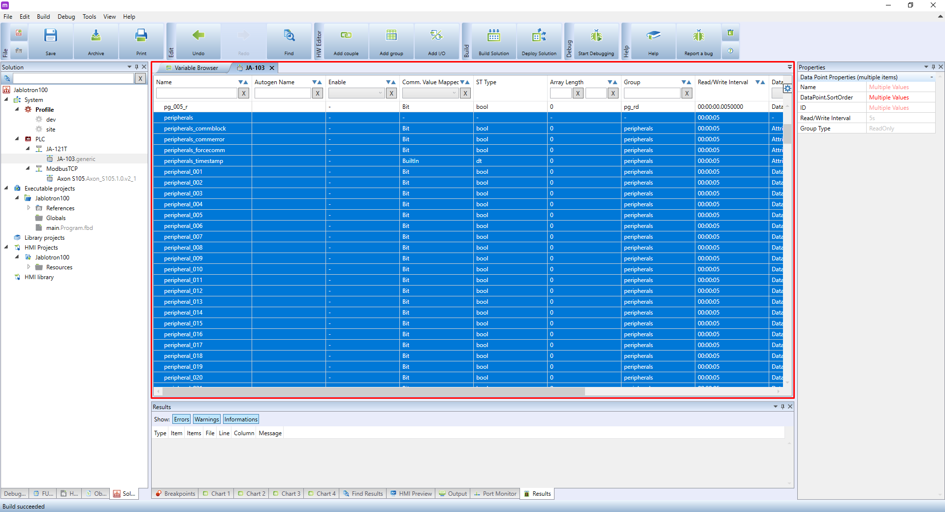
We won’t need any peripherals in this tutorial, as we assume the PGs 1-5 were already mapped by Jablotron service technician. Select all peripherals including their group and press DELETE. If you need to use these peripherals, keep only those data points you will use and delete the rest. In particular, a group named **peripherals** and data points beginning with **peripheral_**.
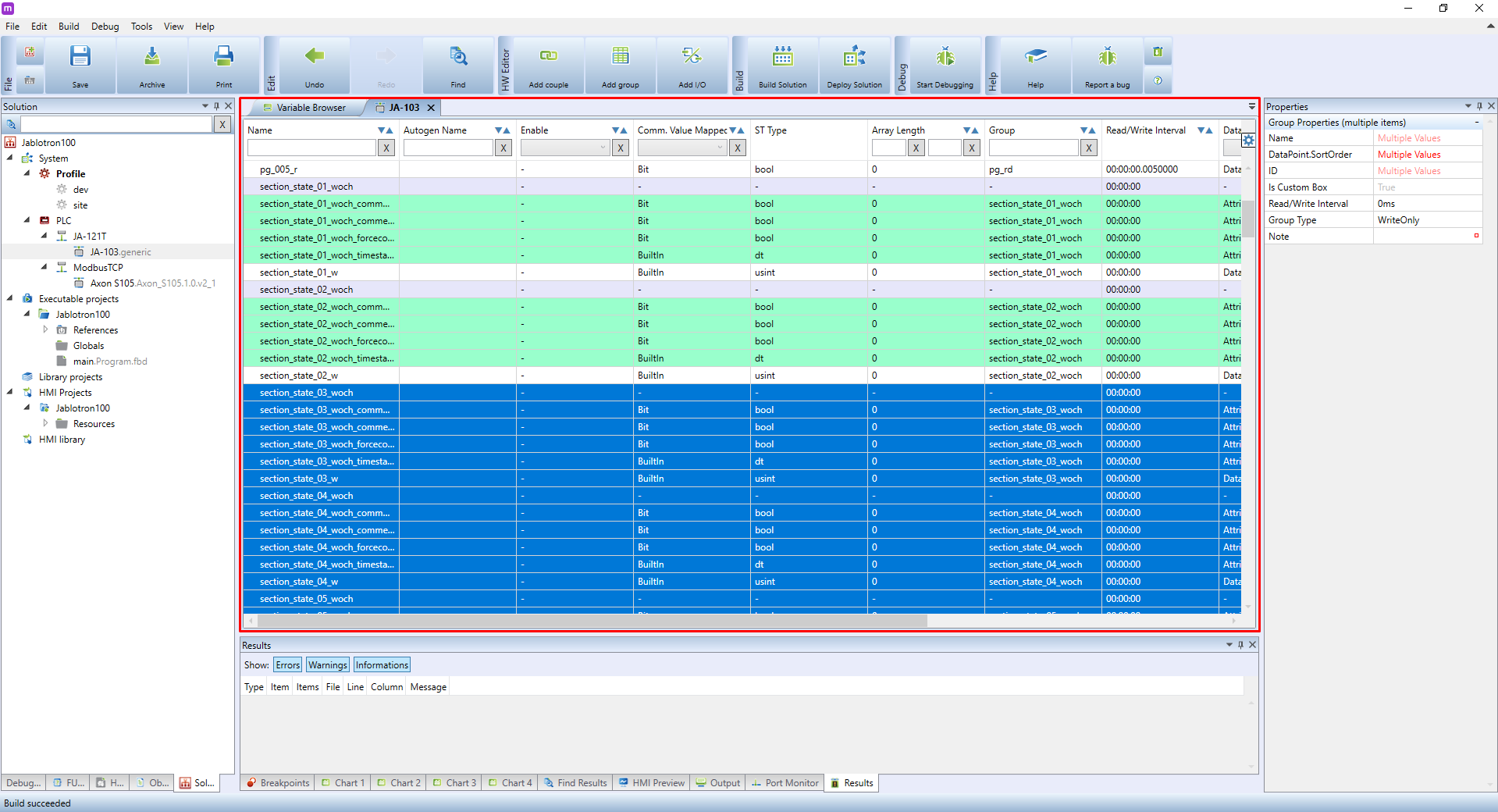
The same process applies to data points for writing into the Control Module. In this case, each data point for writing into sections or PGs is assigned to one individual group. This means you need to delete both the group and its data point including group states. In this case, we need to remove **section_state_xy_woch** and **pg_xzy_woch** groups, and their data points **section_state_XY_w** and **pg_xyz_w** respectively.
Removing these data points is not necessary, as they do not affect the speed of communication. Their removal can, however, make the project cleaner.
Scroll completely down to a list of so-called Couples (yellow background). Couples are connections between both write and read data points, which allows you to read from and write into the datapoint using only a single variable. Couples used for PGs and section states are named **pg_xzy** and **section_state_xy**. You can remove these couples as well.
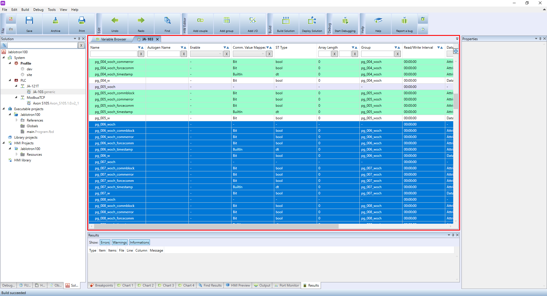
The result should look like this:
{{ :en:sw:01-mervis:Jablotron100_en_21.png?nolink |}}
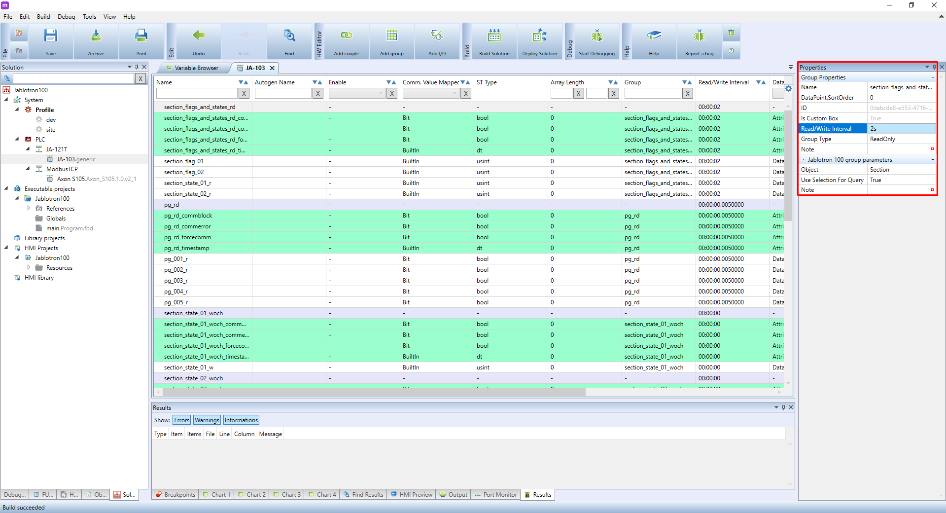
For now, the device is set. In case of more extensive installations, we recommend configuring read/write intervals as well. If errors are detected on the bus (which is indicated while running Debugging mode the variables have a red background in the Variable Browser), it is necessary to increase communication intervals. You can do so by selecting the group you want to modify the interval. Group settings will appear in the right panel. Look for **reading/Write Interval** and change its value. In this case, the interval is not important for write groups, as these groups are updated with each change. After finishing the configuration, deploy the solution again.
Recommended intervals: \\
* Section_flags_and_states_rd ..... 1 s to 5 s
* pg_rd ................................................... 0 to 500 ms
* peripheral ........................................... 5 s to 30 s
For write groups, the interval is not important, as they are by default set to update with each change.
More info about configuring Jablotron devices in the Mervis IDE and a complete description of all data points and/or groups is available in the Mervis IDE help. To open it, press F1.
===== 4 Example of using function blocks and enumerated types =====
Below, you can see an example of an application of the Jablotron 100 ESS in the Mervis IDE. Using this solution, you can trigger lights, acoustical or optical signalization, or send notifications once an intrusion or other alarm is detected. It is also possible to optimize automated tasks (heating, circulation pumps and other comfort systems) when the security system is armed. For emergencies, it is possible to disconnect the power supply in selected parts of the building to prevent any property damage. Last, but not least, the house can lock itself once you leave it. When moving through an unsecured object, you can switch heat pumps or adjust heating based on the current situation.
==== 4.1 Datapoint transformation – SectionTransform ====
Transforms a datapoint from USINT to **SectionState** enumerated type (STRING). The transformation is applied to all couples of **Section_state** data points and is required for using the **SectionFlagsHolder** function block. Conversions are described in the table below:
{{:en:sw:01-mervis:Jablotron100_en_24.png?nolink |}}
==== 4.2 Function blocks ====
The Lib.Jablotron library contains two function blocks for separation of the individual section flags. Both blocks use the **SectionFlags** variable as their input and are designed to indicated section flags (alarm detection, fire alarm, entry and exit delay etc.). These flags determine the type of alarm (fire, intrusion, emergency, sabotage) and allow you to configure your PLC to act on each type of alarm differently (see the [[#example_of_using_function_blocks_and_enumerated_types|chapter’s]] introduction).
If you need to indicate sabotage attempts and you need to hold the ESS alarm until the next section change, you can use a modified variant of the function block named **SectionFlagsHolder**.
The output of these blocks is always of bool type (true/false).
{{ :en:sw:01-mervis:Jablotron100_en_25.png?nolink&170|}}
=== 4.2.1 SectionFlags ===
A block representing an input value of the section’s flags (type **USINT**) on each **BOOL** output, including combinations. The following table describes all monitored bits of the **Flags** input:
{{:en:sw:01-mervis:Jablotron100_en_26.png?nolink |}}
{{ :files:img_breakline.png?nolink |}}
{{ :en:sw:01-mervis:Jablotron100_en_27.png?nolink&170|}}
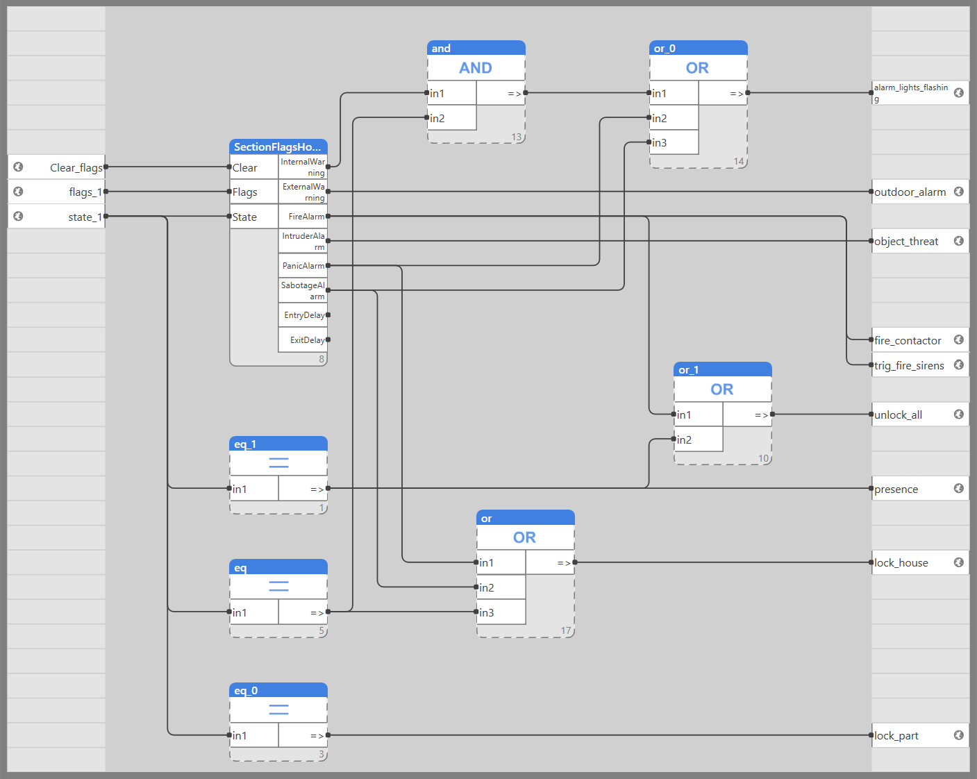
=== 4.2.2 SectionFlagsHolder ===
A variant of SectionFlags with enhanced functionality. A SabotageAlarm output is added along with an automatic sabotage detection –if sabotage is detected, the output is set to TRUE. The main addition is the hold function designed to hold alarms until a change on the State section is detected. This means the block also requires a state input for the monitored section. The block is also extended by the Clear optional input for the option to manually reset all alarms on hold by setting them to FALSE. This input is hidden, and its use is optional.
{{ :files:img_breakline.png?nolink |}}
==== 4.3 SectionState enumerated type ====
=== 4.3.1 ST – structured text ===
The SectionState enumerated type variable is defined by the Lib. Jablotron library. Example of its usage in ST: \\
\\
**Declaration:** Create a variable of the SectionState type). Name it ''State''.
State : SectionState;
**Usage:** to write into the variable, you need to use the ''SectionState#STATE'' format.
State := SectionState#STATE;
=== 4.3.2 FUPLA ===
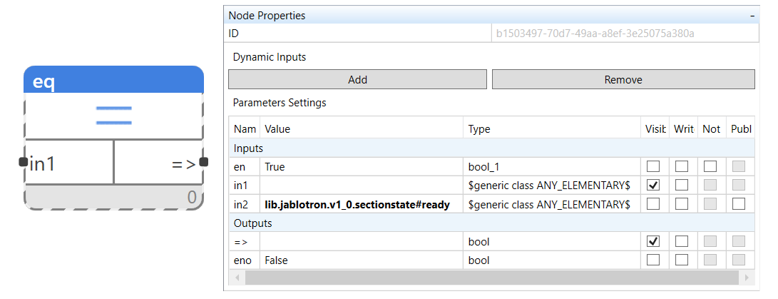
For reading a state from the **SectionState** enumerated type, the **EQ function block** is the most suitable. Connect the Section_state of the selected section to the **IN1** input. On the **IN2** input, set its default value to **lib.jablotron.v1_0.sectionstate#STATE** and hide it.
Replace the STATE value with the SectionState state according to the table in [[#datapoint_transformation_sectiontransform|chapter 4.1]].