Table of Contents
Relay outputs
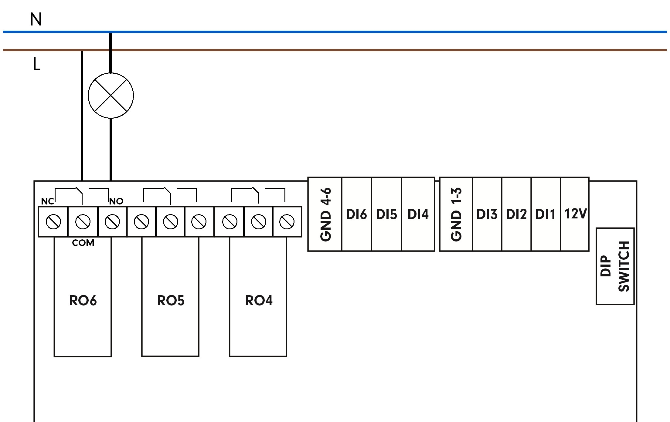
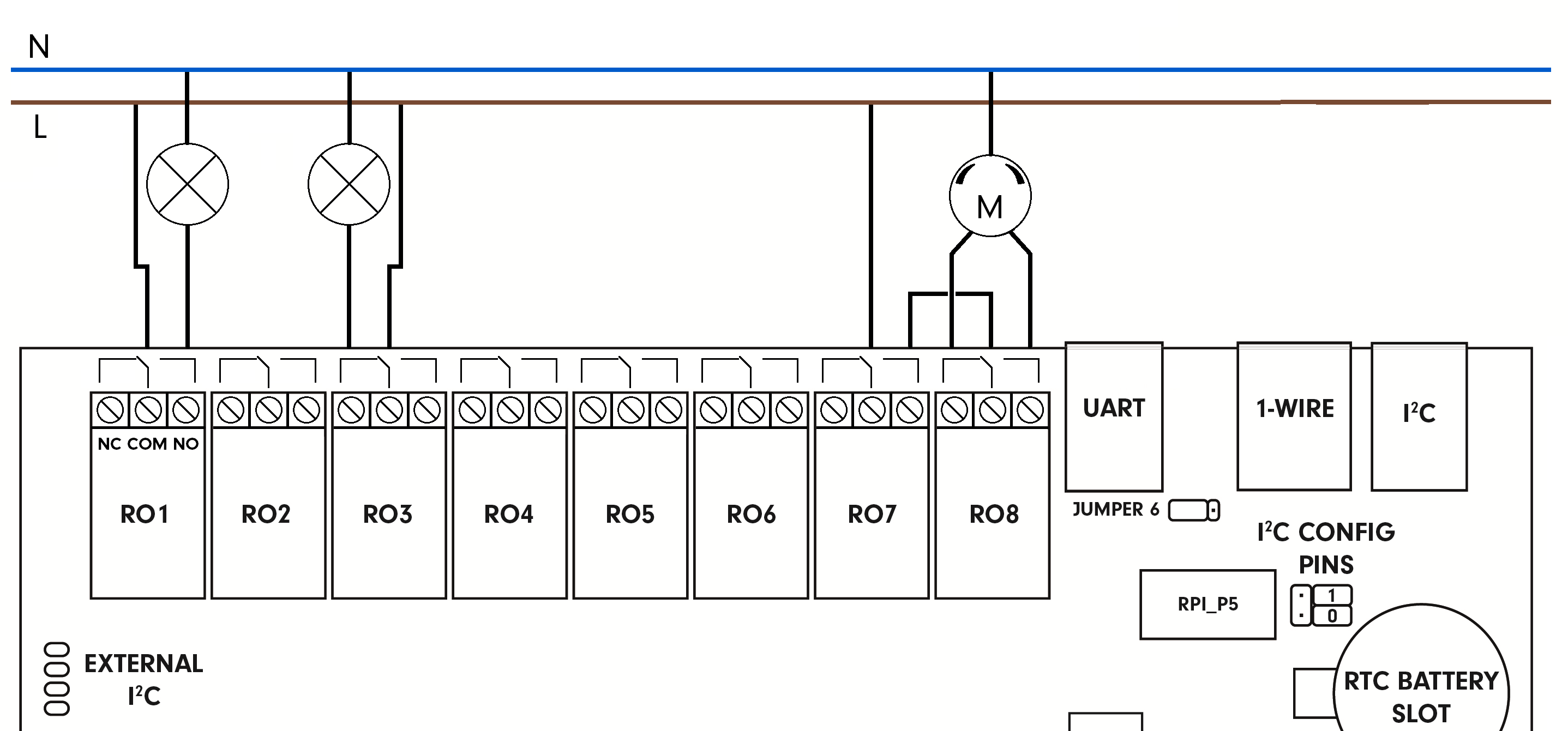
Relay outputs are terminated on terminals labelled by a switch schematic sign and serve for switching two-state devices with alternating or current voltage. The COM terminal is common, serving as input for switching voltage. NO and NC terminals are used as the switching voltage output.
- NO - in the default state (no voltage), contacts are open
- NC - in the default state (no voltage), contacts are closed
Unipi 1.1
The state (On/Off) of each relay is indicated by a LED with a corresponding label. Overload and overvoltage protection should be provided externally by a circuit breaker (ideally one for each output). Nominal current and circuit breaker type should be selected according to the load and its characteristics concerning the maximum current on the output.
Warning:
If an inductive load is connected (e.g., electric motors, relay coils, contactors, or even the cables in extensive electric installations), it is necessary to protect the relay outputs with a corresponding external element (e.g., varistor, RC circuit or a suitable diode).
If a capacitive load is connected (e.g., power sources of LED lights), it is necessary to protect the relay contacts against inrush current by connecting a corresponding thermistor to the relay's output.
 Detailed information can be found in the product datasheet provided by the relay manufacturer: