Table of Contents
Debounce


This function works only for following Inputs & Outputs:
- digital inputs
How it works
The debounce functionality is for catching glitches which typically occur when changing states on the digital input. Those happen mostly when the digital input is operated by some mechanical element, e.g. momentary switch. The signal generated upon pressing and releasing a momentary switch can look like this:
 Note that the bounces shown above are exaggerated and typically are measured in hundreds of μs.
To “debounce” these glitches, you have to slow down the reaction on changing states of the input. On HW level you could achieve this by employing an RC element. To make your life easier, you can set this “slowing down” on SW level. We will call “debounce time” as the smallest period between rising and falling edges, after which change can be acknowledged as valid. Impulse (rising edge) is processed as valid only in case it equals logical 1 for the whole debounce time duration.
Changing the debounce time
Now let's see how debounce can be configured in the Mervis IDE. The debounce settings can be found in device inputs, so right-click on the name of your Unipi controller under the Modbus TCP channel and select Open Editor. A tab with all controller registers will appear.

Under the Name field, you will find a search bar in which you enter DI_. A list of all available digital inputs, or more precisely their data points, is displayed.
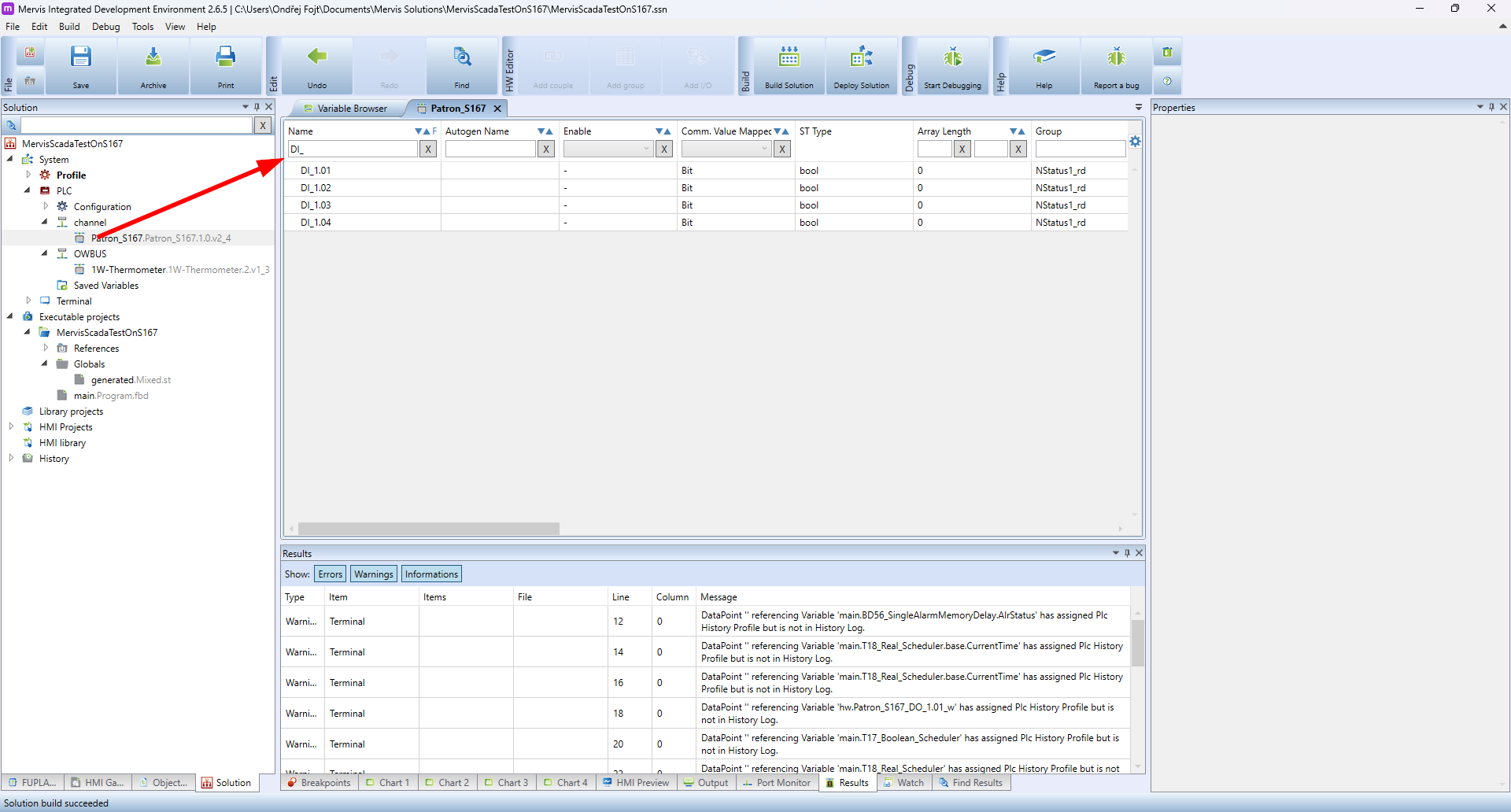
Select one or more desired digital inputs, for which you want to change the debounce time. In the Properties panel you can see all the options you can set on these registers. The option we are interested in right now is the Debounce. The value of this option is represented in ms(milliseconds) of deboucing period.
Note:
All digital inputs are set to 5 ms debounce time by default, which means digital inputs will ignore changes shorter than 5 ms.


Important:
We just changed the configuration of the PLC modules, which is not applicable by simply uploading the solution. To save the configuration, follow the Unipi - Configure Module tutorial.