This is an old revision of the document!
UniPi 1.1
Hardware description
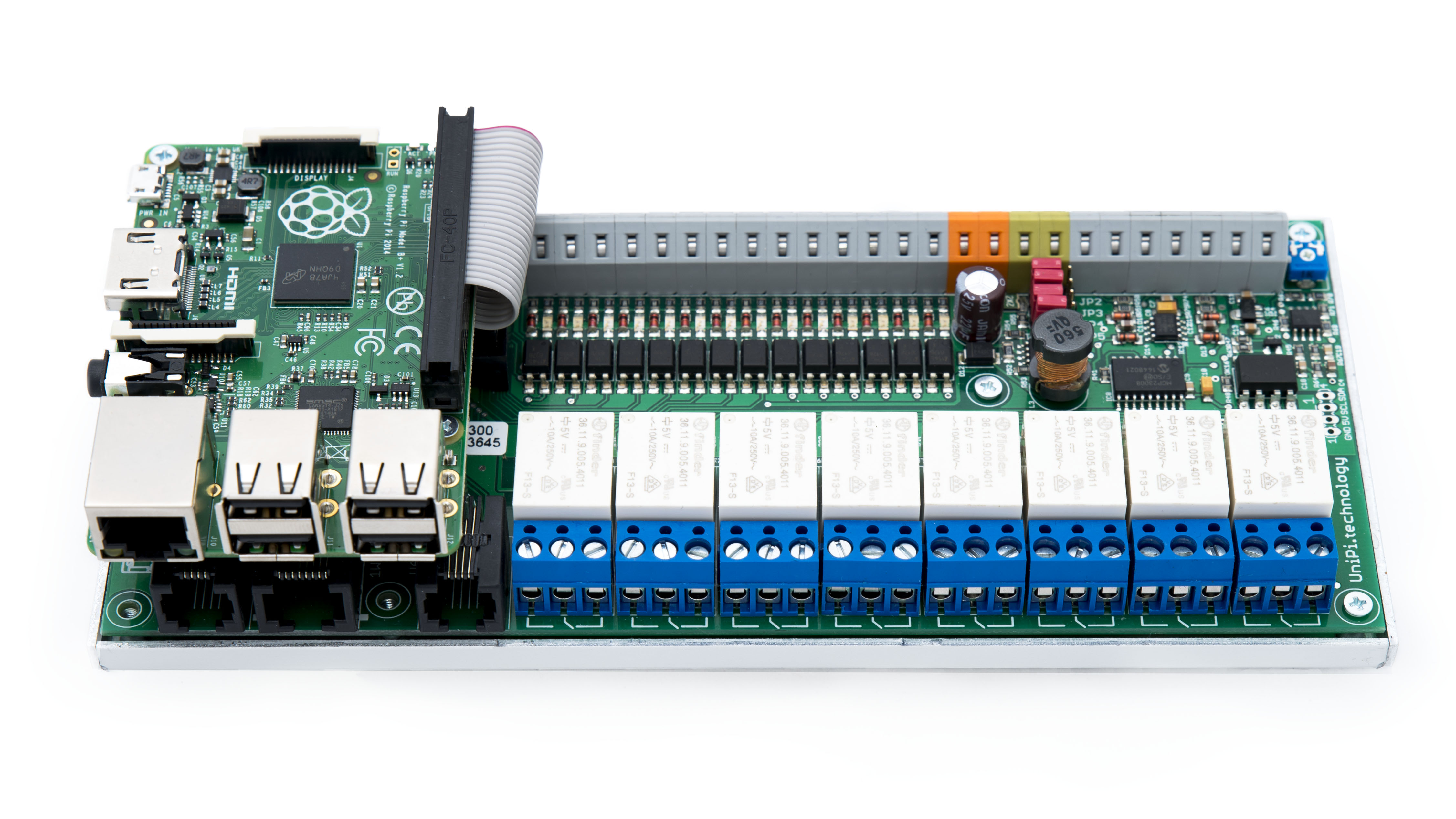
UniPi 1.1 is an extension board for Raspberry Pi. The board allows the Raspberry Pi to function as a programmable logic controller (PLC) in a variety of automation applications.
User manual
Overview
Raspberry Pi Model 3B computer is used as CPU. The computer is connected via its GPIO through ribbon cable, processes all data from I/O modules and is sending responses. All individual I/Os and communication interfaces are connected to the Raspberry Pi's CPU either directly via GPIO or indirectly via I2C. Raspberry Pi also provides network connectivity and USB ports.
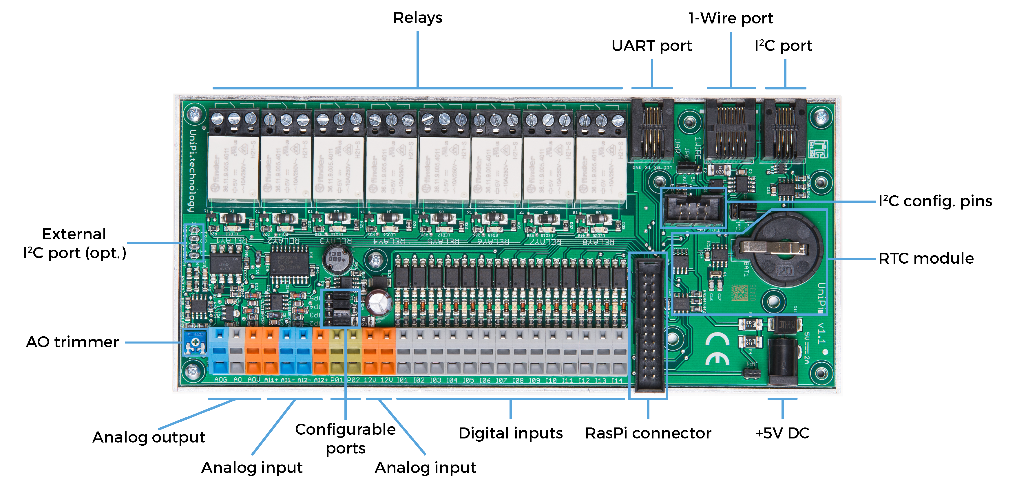
The UniPi 1.1 feature following inputs & outputs
- 8x Finder 36.11.9.005.4011 changeover relays (rated for 250V AC/5A or 24V DC/5A)
- 12x galvanically isolated digital inputs (5-24V DC voltage, 5 ms minimum pulse lenght)
- 2x 0-10V analog inputs
- 1x 0-10V analog output
- 1 × 1-Wire port for connection to 1-Wire thermometers and other sensors
- 1 × I2C port for expansion
- 1 × UART port for external serial communications
- socket for RTC (real-time clock) battery
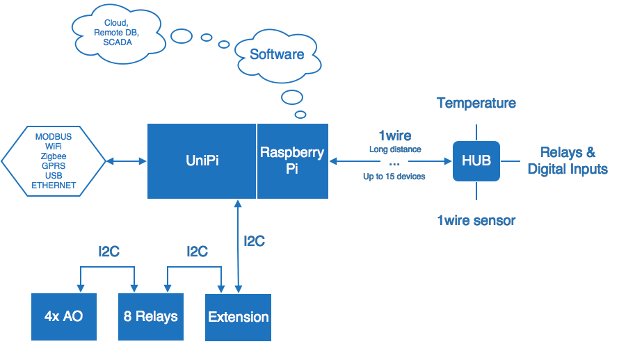
The I2C port supports connection of extension modules, such as the EMO-R8 relay extension.
The 1-Wire bus is used for passive reading of data from corresponding 1-Wire sensors (humidity sensors, temperature sensors etc.). One bus can receive data from up to 15 sensors at once (provided a suitable 1-Wire hub is used).
Note: UniPi 1.1 requires an external 5V 2.5A power source with 2.1mm DC jack.
Inputs & outputs
Each I/O type on the UniPi 1.1 has its specific use. As the UniPi 1.1 features a several types of I/Os, it represents a highly flexible controller suited to a variety of different automation tasks.
Digital inputs are designed for reading of binary values (0/1, on/off, open/closed etc.) and are thus suitable for connecting switches, motion sensors, window or door magnetic locks etc. Each input features a LED state indication.
Digital outputs can be used to control binary state devices, such as lightning switches, window shutters control, remote door control etc.
Analog inputs are used to receive either 0-10V voltage or 0-20mA current signals. Alternatively, they can be used for reading data from corresponding sensors, such as resistance thermometers. The user can adjust the input mode via corresponding control software.
Analog output can be used for control of external devices such as three-way valves or heat exchangers via 0-10V voltage or 0-20mA current signals.
Relay outputs are designed for switching two-state devices via alternating or direct voltage. Relays thus can be used to switch boilers, water heaters, electric motors or other stronger relays. Each relay features a LED state indication.