Mervis IDE
Mervis IDE (integrated development environment) is the cornerstone of the Mervis platform. It allows you to:
- Connect to units, even remotely over the internet
- Manage the configuration of units including updates of Mervis RT
- Create libraries of functions and Modbus devices to easily reuse them in another projects
- Build web-based HMIs (human-machine interfaces)
- Create projects for Mervis SCADA - environment for remote installations management
- Detect connected 1-Wire sensors and Unipi Extensions
- Upload and debug the solutions to units running Mervis RT
- … and many more
The project in Mervis IDE is called a solution. The solution consists of connection parameters to your units, their configuration, programs, libraries and HMI interfaces.
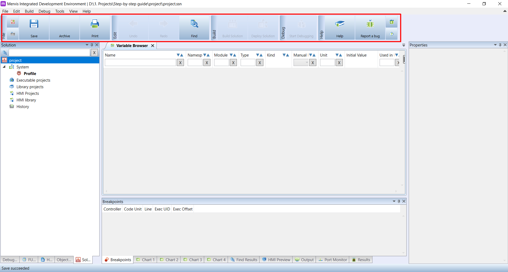
On the next screenshot, you can see a typical workspace of a project in Mervis IDE
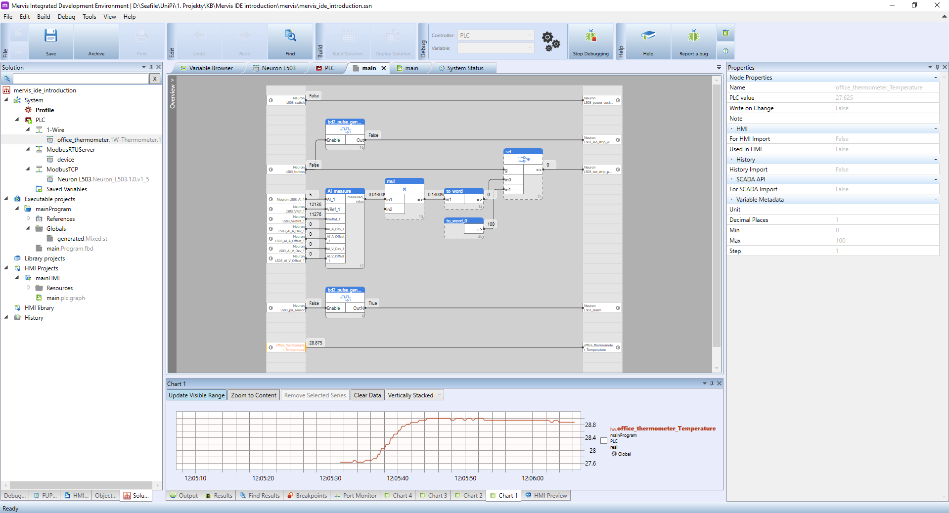
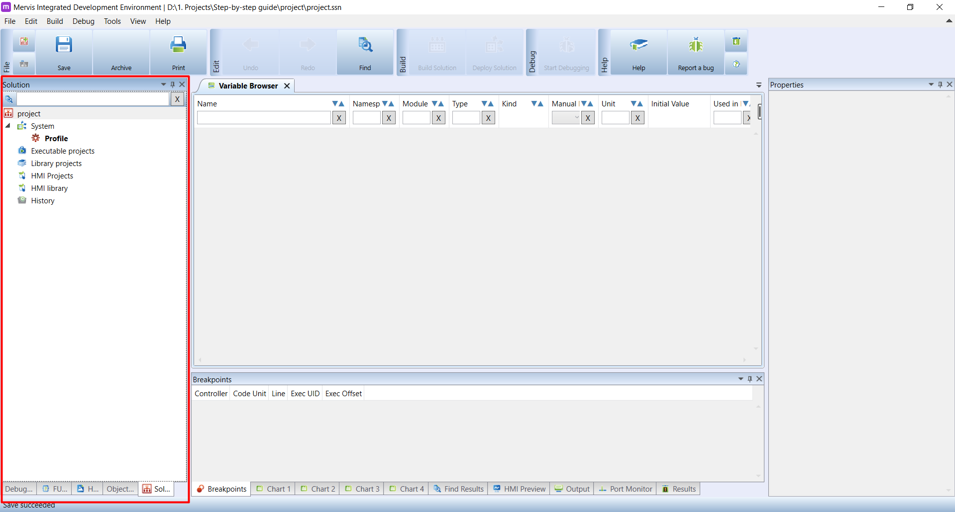
In the Left panel, called Solution, you can see the expanded tree for unit (PLC), containg a list of configured communication channels (1-Wire, Modbus) and connected devices. In the Executable Projects you will have all your programs and function libraries. In the HMI Projects you can see a list of HMI interfaces.
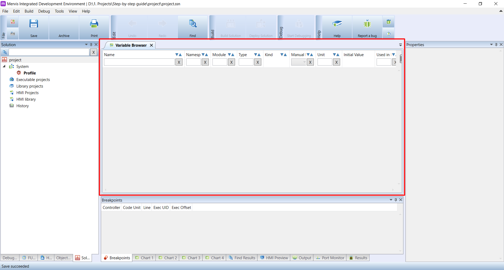
In the Main window, you can see a FBD program while in the debugging mode. The left column of the programming workspace contains inputs of the program. In the middle section, you can place function blocks (FBs), which enclose a certain functionality. The right column contains outputs of the program. As stated above, the program is in the debugging mode, which allows us to check the current values of inputs, outputs and variables in the unit as well as override their values. Those values are shown in small grey boxes right next to the input/output. The debugging mode also allows you to chart the actual values, as you can see in the section under the Main window.
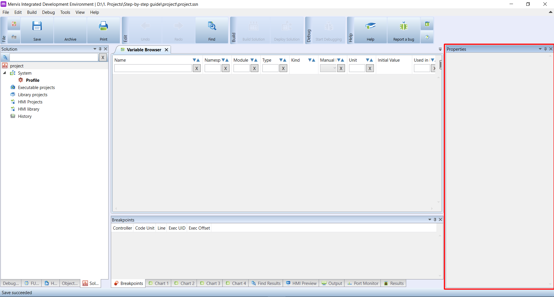
The Properties panel on the right contains a complete list of all properties for the selected object. Right now, it shows parameters for office_thermometer_temperature input.
Mervis HMI
On the next screenshot, you can see interface used to build the HMI.
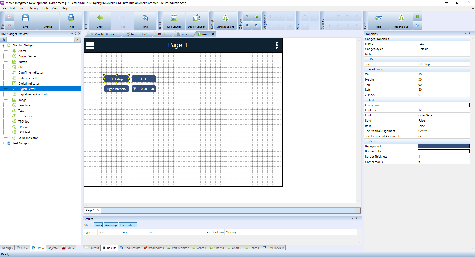
In the Left panel, you can see a list of graphical elements, you can use for building your interface. The Main window shows a workspace for the actual HMI interface. In the Properties panel you can see properties of the selected text element.