This is an old revision of the document!
SSCP to SQL Bridge
This daemon-based service allows bi-directional data transfer between an Unipi PLC running Mervis and a SQL database through an SSCP protocol (the proprietary protocol used by Mervis runtime and Mervis IDE). The daemon can run anywhere - on the system with Mervis runtime running, on the same system as a database server or another remote machine.
Installation scenarios
- Daemon runs on the PLC
- In this case the daemon runs on the PLC right next to the Mervis RT and send the data to a remote database. Requires IP connection between the PLC and the database server.
- Daemon runs a different machine/server
- This can be divided into two scenarios depending on the network connection.
- Daemon has IP access to the PLC
- This is the reverse installation of the first case, where the Daemon runs on the PLC.
- The Daemon is installed to a server and communicates with the PLC and send the data to the database server.
- The database server can run on the same server as the daemon or totally different machine.
- Daemon does NOT have IP access to the PLC
- This option will be available soon
- This scenario uses Mervis Proxy server to read the data from the PLC and send them to the database server. The advantage is that the Daemon does not require IP access to he PLC so the server running the Daemon can be on the other side of the World (behind NAT or firewall limiting access to the internal network).
- Requires the PLC to be connected to the Proxy server.
- Limited by the speed of the Proxy.
Supported operations
- SELECT - This action will read a row from the specified table and force the values to the relevant Mervis variables within the PLC. The row can be specified using the “where” parameter, which will be directly used as a “WHERE” clause in the SQL query. (Set Mervis variable according to the DB)
- UPDATE - This action will update a row in the specified table with the variable values in the PLC. The row can be specified using the “where” parameter, which will be directly used as a “WHERE” clause in the SQL query. (Set DB row according to the Mervis variable)
- INSERT - This action will insert a row with current PLC values into the specified table each time the variable state is read from the PLC. (Log Mervis variable to the DB)
Supported platforms
- The program is designed to work on both x64 and ARM* platforms including all Unipi PLCs.
- The SW is distributed as a binary Debian (.deb) package tested on the Debian 9/10 based Linux distributions.
- As the SW is not an open-source product, contact Unipi support in case you need to operate the SW on another platform.
*Currently arm64 and armhf are supported
QUICK START GUIDE
Installation
- Add the Unipi Debian repostiory into your apt-sources list (skip this step if you are working with an Unipi PLC). Replace the <distro> placeholder with your Debian distribution name – stretch or buster.
Mervis IDE (integrated development environment) is the cornerstone of the Mervis platform. It allows you to:
- Connect to PLCs, even over the internet
- Manage the configuration of PLCs including updates of Mervis RT
- Create libraries of functions and Modbus devices to easily reuse them in another projects
- Build web-based HMIs (human-machine interfaces)
- Detect connected 1-Wire sensors and UniPi extensions
- Upload and debug the solutions to PLCs running Mervis RT
- … and many more
The Mervis IDE work project is called a solution. The solution consists of connection parameters to your PLCs, their configuration, programs, libraries and HMI interfaces.
On the next screenshot, you can see a typical workspace of a Mervis IDE solution
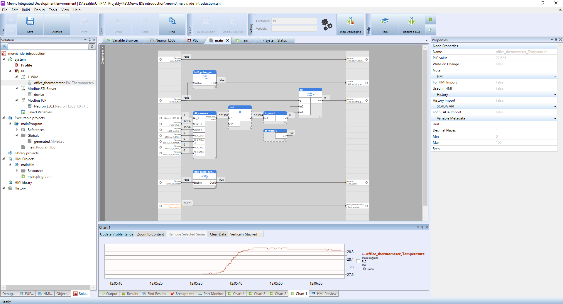
In the Left panel, you can see expanded tree for PLC, showing a list of configured communication channels (1-Wire, Modbus) and connected devices. In the Executable Projects you will have all your programs and function libraries. In the HMI Projects you can see a list of HMI windows.
In the Main window, you can see a FBD program under the debugging mode. The left column of the programming canvas contains inputs of the program. In the middle section, you can place function blocks (FBs), which enclose a certain functionality. The right column contains outputs of the program. As stated above, the program is in the debugging mode, which allows us to check the current values of inputs, outputs and variables in the PLC. Those values are shown in small grey boxes right next to the output. The debugging mode also allows you to chart the actual values, as you can see in the section under the Main window.
The Properties panel on the right contains a complete list of all properties for selected object. Right now, it shows parameters for office_thermometer_temperature input.
On the next screenshot, you can see a the HMI building interface.
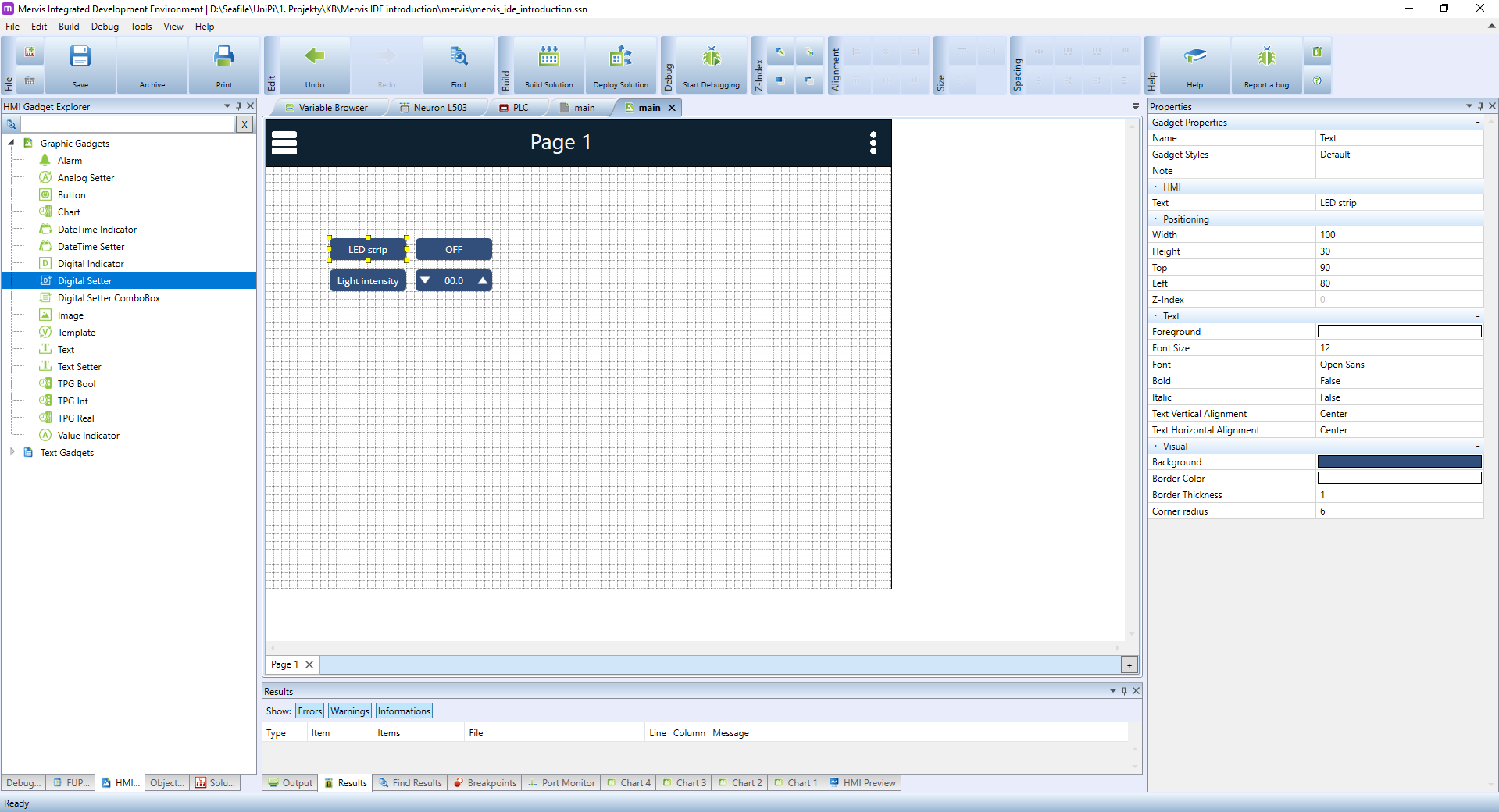
In the Left panel, you can see a list of graphical elements, you can use for building your interface. The Main window shows a canvas for the actual HMI interface. In the Properties panel you can see properties of the selected text element.