This is an old revision of the document!
Working with Autogen
One of the most important thing you need to know about MervisIDE is what is Autogen and how to work with it. In previous tutorial, we learned that Autogen is for accessing HW inputs and outputs from the program. We also discovered, how to Set Autogen on the whole device (PLC, Extension, Modbus device, 1-Wire sensor,…). Let's discuss it a bit more.
Why not to Set Autogen on the device
Setting Autogen on whole device is a nice feature for debugging. You tell the Mervis Runtime to poll all the inputs and outputs and you have them immediatelly accessible in your program and in the debugging mode. The downside of this is a hit on the performance of your program. The PLC contains a lot of informations, which are needed in special cases and you don't need them for normal operation. Also polling unnecessary information from the Extensions over slow RS485 bus will have significant impact on the performance.
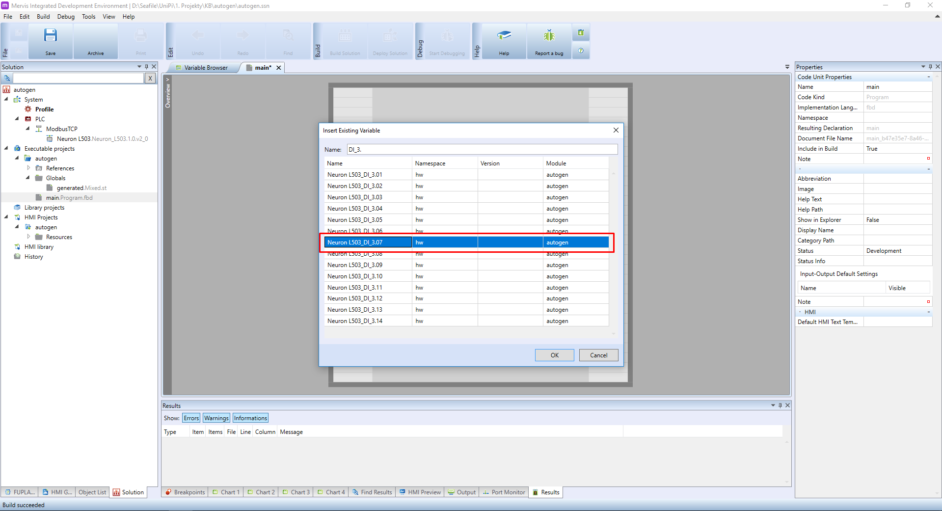
The other downside is that the Set Autogen will automatically generate the name of the variable. As you can check, the generated name consists of UniPi unit name and the name of the input/output. In our project we have attached the Neuron L503 and we want to use the digital input 3.7. The generated name is “Neuron L503_DI_3.07”.
You can quite happily use this variable in your program, even multiple times (the button can control many aspects of your project at once). One of the problems with this naming is that it is not descriptive. When you are working on the project, you will remember that DI 3.7 is connected to the “OK” button on the operator's panel, or to the wall switch in your bedroom. In half a year, you wouldn't have to. Or the project will be handed over to somebody else who will not have that knowledge and the project will be hard to read.
Another problem is the automatic inclusion of the PLC name into the name of the variable, in our instance the prefix “Neuron L503_”. If you have only one PLC in your solution, that may be OK. It can get unreadable, when you have more PLCs and even more unreadable, when you have more PLCs of the same type. It is a good idea to rename them according to some rule. Typically, the name is based on the physical location - boiler_room, 1st_floor or operator_panel.
We advise to name the variables and PLCs using lowercase alphanumeric characters (a-z,0-9) and underscore (_) as a word delimeters: boiler_room, bedroom_blinds, 1st_floor_temperature,…
For making fast and readable projects, the Mervis includes functionality for renaming the inputs/outputs and PLCs to your liking. Let's create a simple project where we will demonstate it. Our project will need one digital input (DI1.1) which will be used for reading a state of a button. And we will need one digital output which will be wired to a LED indicator.
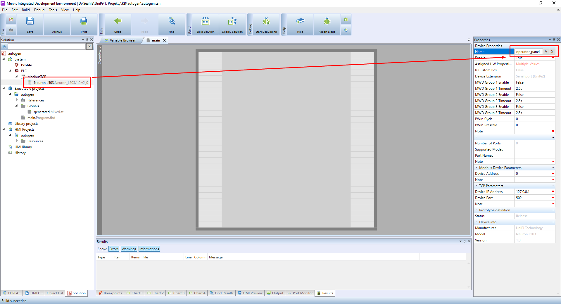
Let's start with renaming the PLC. Select the PLC in the Left Panel and head over to the Properties. Change the property “Name” to “operator_panel” and confirm by clicking on V.
Next, we will renamen the inputs and outputs. Double click on the prototype in the Left panel and head over to the list of IOs which will appear in the Main Window and search for the name “DI_1.01”:
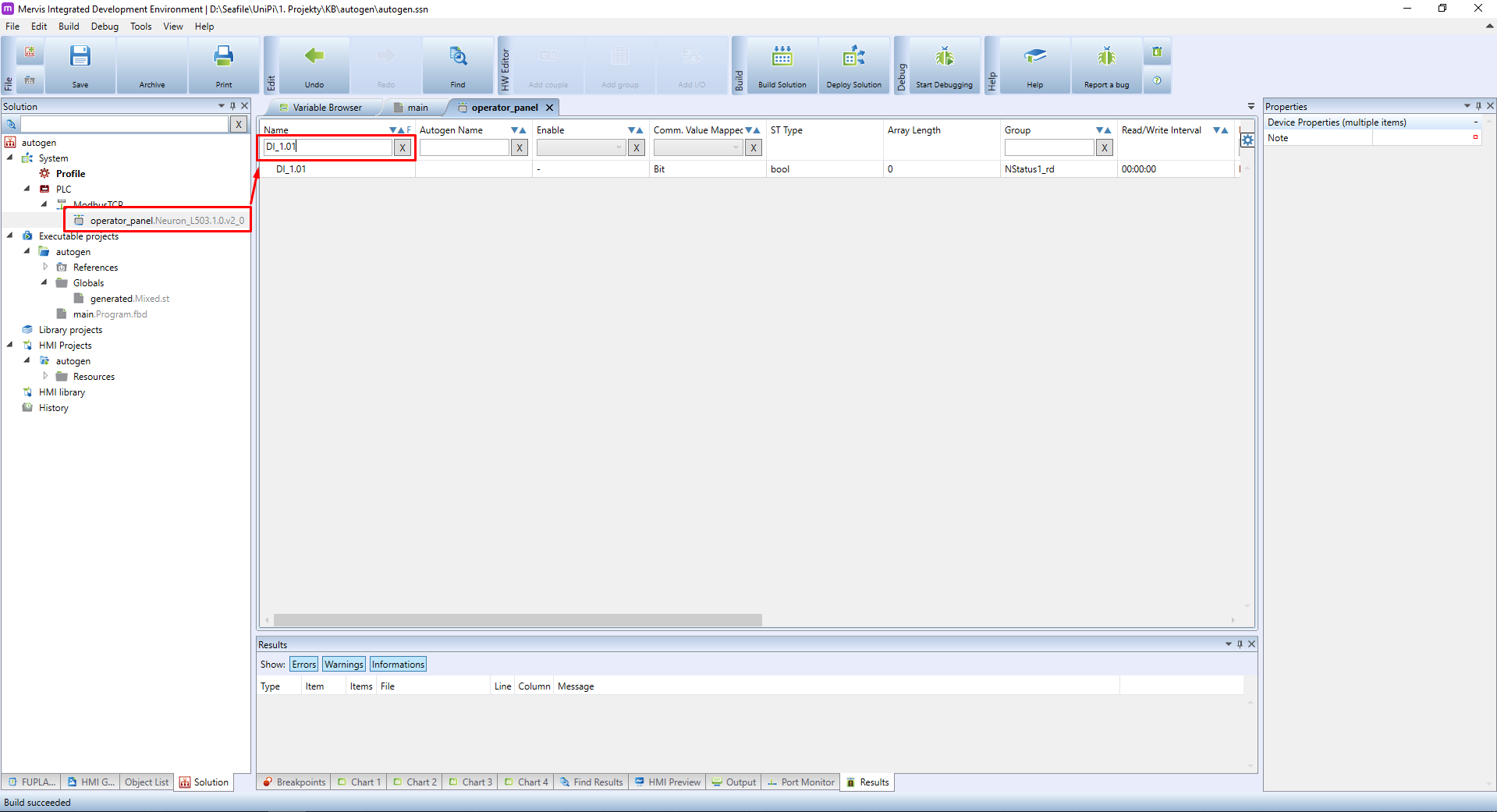
To rename the input, fill the value in the column “Autogen Name” and confirm by clicking on V. The DI_1.01 is for button, so let's rename it to “button”.

Now set the autogen for this datapoint. Right click on the datapoint and in the context menu click on the “Set Autogen” and confirm the dialog by clicking on OK.
Repeat this process for the digital output. The DO_1.01 will be called a “led”.
As you will find out, the digital outputs (DOs) have two datapoints available: DO_X.Y_w and DO_X.Y_r. For now, use the DO_X.Y_w and we will explain the difference in future tutorials.
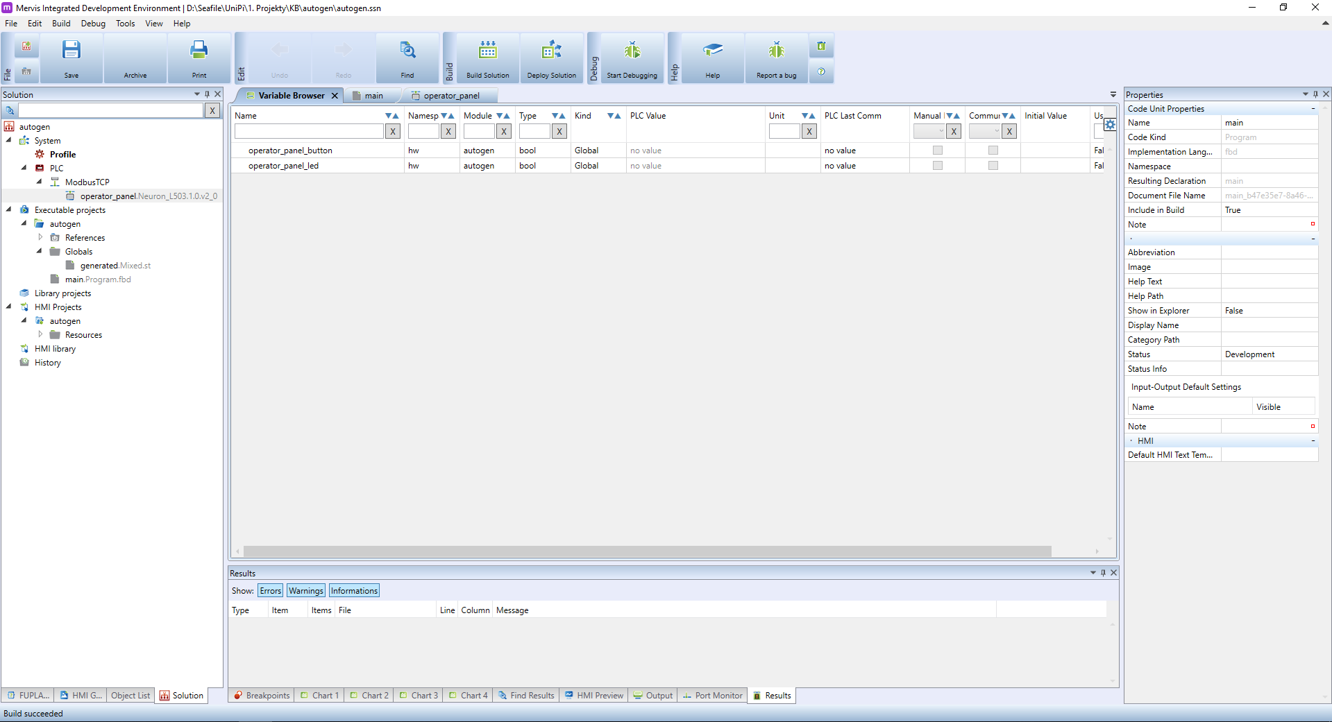
By setting autogen on two datapoints we created two global variables. One of the places, where you can check it is the Variable Browser tab of the Main Window.