State mapping - HMI, SCADA, History
An item for configuring parameters of displayed states in HMI schemes and other interfaces. As such it is located in data point properties or in elements used in HMIs.
Patron
Neuron
Gate
Unipi 1.1
Axon
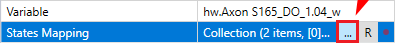
The menu can be opened by clicking the  button next to the state mapping
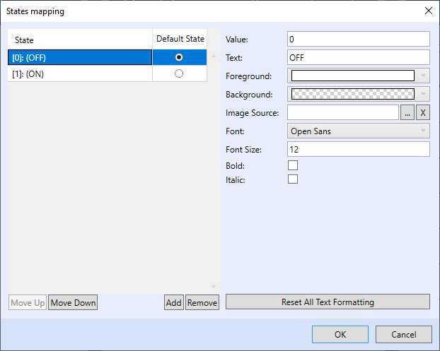
In the state mapping menu, you can add states by clicking the Add button. You can set its value and the visible name. Settings differ depending on the state’s use.
History log
History log allows you to set a name for any value (state) of variables stored in the log. By doing so you can make the DB graph much clearer, especially when a large number of variables is displayed.

Note: Two-state values are by default set to TRUE/FALSE. These states are not displayed in the state mapping window, eg. if the mapping is empty, the default values are used.
Graphic Mervis HMI
With graphic HMI templates, users have much broader options of state mapping including text colour, background colour, picture or other additional text settings. As these settings apply only to the specific state, we recommend using similarly sized pictures for all states.
Mervis SCADA dptable
Settings are nearly the same as with the graphic HMI, graphic properties are however not available. You can set them easily through values or as a bitmask.
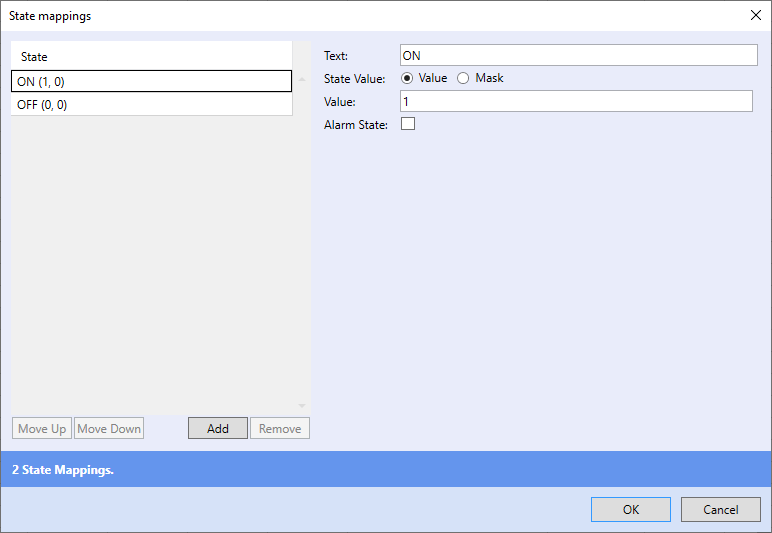
If you need to monitor bit combinations and not their values, you can use bitmask settings. This variant can be used only in the Mervis SCADA dptable.
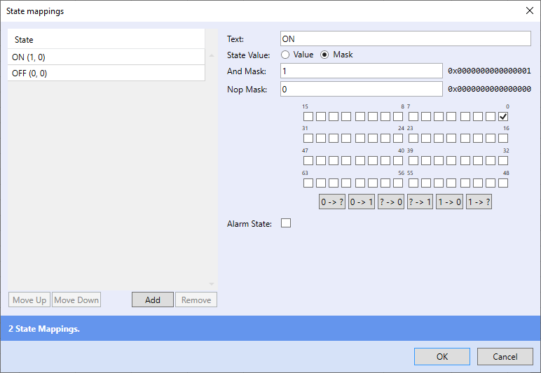
Bitmask can be used for indication of multiple values, or a combination of bits using a single state. AND mask is valid if the individual bits of the variable matches the mask. Each checked field marks one valid bit (TRUE), an empty field marks invalid bit (FALSE). Black fields represent indefinite value of NOP mask, eg. the field can contain any value. If the AND mask is valid at the same time, the state will become valid.
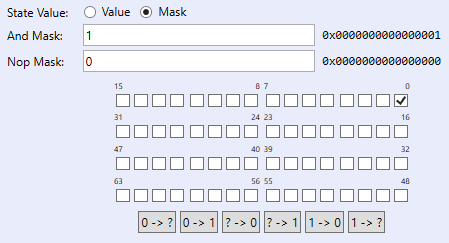
According to the picture above the state is valid if the value will be greater or equal to 8 and lesser than 16.
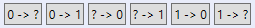
Function of the individual buttons:
0 -> ?
Sets all empty fields of the FALSE definite state to indefinite state
0 -> 1
Sets all empty fields in the FALSE definite state to the TRUE definite state
? -> 0
Sets all fields of the indefinite state to FALSE with the exception of TRUE definite state fields
Does not affect the AND mask
? -> 1
Sets all indefinite state fields into the TRUE definite state
1 -> 0
Sets all TRUE definite state fields to FALSE
Affects the NOP mask
1 -> ?
Sets all TRUE definite state fields to an indefinite state