Warning:
Prior to mounting, make sure that the environment is disconnected from all power sources.
If the holder for DIN rail is not installed, it must be mounted first with the supplied screws (3x M3x5, flat head) so that the spring is towards the top of the device.
DIN holder installation

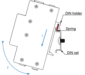
To install unit on the DIN rail, slide the unit onto the rail from above (in the direction of arrow 1 in the picture below), against the spring resistance downwards and then clicking the lower part (in the direction of arrow 2 in the picture below).
Mounting on DIN rail

Attention:
Avoid pressure on the terminals as they could be mechanically damaged.

Caution:
Make sure that the upper edge of the DIN rail runs between the spring and the rear of the DIN holder (see figure above). Improper mounting of the DIN bracket can cause injury when mounted on the DIN rail.
Note:
The operating latch can be locked in 4 positions in the base, one of which is not compatible with Unipi Edge. To ensure that any alteration to the locking position is carried out easily and safely, when the base is being inserted or removed its upper section should be pressed in gently by hand. At the same time the operating latch must be pushed out. This also prevents any possible damage to the locking lugs in the latch guide.
Warning:
Prior to mounting, make sure that the environment is disconnected from all power sources.
If the holder for DIN rail is not installed, it must be mounted first with the supplied screws (2x M3x7 mm, button head) so that the hook of the extension spring is on the bottom and facing towards front of the device.
DIN holder installation

To install unit on the DIN rail, slide the unit onto the rail from above (in the direction of arrow 1 and 2 in the picture below) and then pull the extension spring down with screwdriver and lightly push the device (in the direction of arrow 3 in the picture below) until flush with DIN rail.
Mounting on DIN rail

Attention:
Avoid pressure on the terminals as they could be mechanically damaged.
Warning:
Prior to demounting, make sure that the unit is disconnected from the power supply.
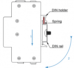
Demounting of the unit is done with opposite procedure, i.e. hold the unit with both hands and push it down, against the spring resistance (in the direction of arrow 1 in the figure below). Then pull the bottom edge of the unit towards you (in the direction of the arrow 2 in the picture below).
Demounting from DIN rail
Attention:
Avoid pressure on the terminals as they could be mechanically damaged.
Warning:
Prior to demounting, make sure that the unit is disconnected from the power supply.
Demounting of the unit is done with opposite procedure, i.e. insert screwdriver into the extension spring of the DIN holder and push it down, against the spring resistance (in the direction of arrow 1 in the figure below). Then pull the bottom of the unit towards you (in the direction of the arrow 2 in the picture below).
Demounting from DIN rail

Attention:
Avoid pressure on the terminals as they could be mechanically damaged.
Attention:
Replace the battery only at your own risk! If you are not sure about the procedure, please contact technical support first.
Warning:
Before replacing the battery, make sure the environment and equipment are disconnected from all voltage sources.
When the battery is pulled out the RTC will lose power thus clearing the system time. After the battery is changed the device can set its time automatically if it is connected to internet. Otherwise the time must be set manually.
Follow these steps to replace the internal lithium battery:
Unscrew all the screws on the sides of the chassis

Gently pull out the side where the USB port(s) are located (in the direction of arrow 1 on the picture below) and then rotate the side upward (in the direction of arrow 2 on the picture below)
Attention:
Do not try to forcefully separate the two parts, as they are connected by wiring!


Remove the lithium battery by pulling it up and out of its casing. This action may require a lot of force. To prevent any damage to the battery casing, make sure to pull the battery straight up, not to the side
Attention:
If any tool is used to remove the battery, it is important to make sure that the tool is isolated and cannot create a short-circuit.

Insert the new CR2032 lithium battery into the empty casing
Attention:
Pay close attention to the battery's polarity and the markings on the casing!
Reassemble the chassis using the reverse procedure from step 2.
Note:
If the flat grey cable connecting the top and bottom parts becomes disconnected, it can be reconnected by aligning the red stripe on the cable with the white circle near the terminal.
Secure the two parts back together with the screws on each side
Caution:
Danger of explosion if battery is replaced by wrong type. Replace battery only for the same or equivalent type recommended by the manufacturer.
Disposal of lithium batteries:
Do not dispose of lithium batteries in communal or general waste. Dispose of the battery according to local regulations and law relating to disposal of these materials (e.g. in collection points allowing dispose of batteries).
Special instructions for manipulation and disassembly
If it is possible, disassembly and assembly this device only in workplaces protected against electrostatic shock (EOS/ESD).
If ESD protected workplace cannot be guaranteed, then it is very important that the user is electrically discharged before touching the device by hands or tools.
This can be easily done by touching any grounded metal part of enclosure.
This device is sensitive to electrostatic shock:
Electronic boards and their components are sensitive to electrostatic discharge.
It is necessary to be extremely careful while checking and manipulating with the device to ensure its integrity.
Unipi devices are designed and manufactured to closely meet the requirements for environmental protection.
Do not dispose of the device in municipal waste - it contains electronic components that are recyclable.
Dispose of the device in accordance with local waste disposal regulations.
You can return the used device at designated e-waste collection points.
This device is in accordance with WEEE directive.
Waste Electrical and Electronic Equipment directive (WEEE) aims to:
Reduce the waste from Electrical and Electronic Equipment (EEE).
Introduce responsibility to EEE manufacturers for environmental impact of their products, especially at the end of the products life.
Support the separate collection, processing, reusability, usage, recycling and ecological disposal of EEE.
Prevent potential negative impacts on environment and human health from dangerous substances in EEE and to recycle and reuse its materials.
WEEE Directive Statement for the European Union:
This device cannot be disposed of as municipal waste. Different rules for handling electric waste may apply in other jurisdictions.