Table of Contents
Digital inputs
Digital inputs serve for an indication of TRUE/FALSE logic states and can be also used as counters to collect data from pulse meters, monitor engine revolutions etc. Another possible application is to connect input and output using the DirectSwitch function.
TRUE logic state (switched on) on input is indicated by LED with the corresponding marking matching the input label.
The software detects TRUE state if the input voltage between the given DIx and DIGND terminals is in range of 7-35 V⎓. If the voltage decreases below 3 V⎓, the FALSE state is indicated. The voltage between 3-7 V⎓ is detected as a non-defined state.
Connection
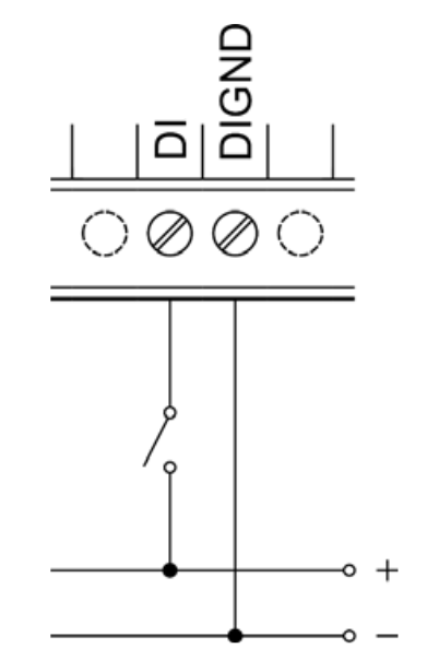
Each connector with digital inputs features a common DIGND terminal for connection of DC power source negative pole. The positive pole of the power supply is to be connected to the DIx or DIy.x terminal through the connected external device. See the following image for illustration:
Note:
For connection of external devices to digital inputs, we recommend using a different (separate) power supply from the one used to power the device (unit/Extension) in order to retain galvanic isolation. Each digital input group also feature a DIGND terminal added specifically for connection of the separate power supply negative pole.
Special functions
Aside from the standard inputs and outputs, Neuron units also feature additional functions for broadening the possible applications, performance optimization and monitoring of the entire project. These functions run directly in the I/O section's microprocessor, making them independent on the control software.
Debounce
Function Debounce serves for input flash repression, its value is presented in hundreds of μs (i.e. value 10 equals 1 ms). Impulse (rising edge) is processed as valid only in case it equals logical 1 for the whole set duration.
Counter input
One of the most interesting functions is counter input - a high-speed rising edge counter independent on the control software. Simply put, the counter can very accurately detect even very short pulses.
Counter inputs are suitable especially for collecting data from energy meters, water meters, gas meters and other pulse meters installed in HVAC systems. They are also useful for reading engine revolutions. For this purpose, Unipi units feature 64-bit registers. When the maximum value of the counter (4 294 967 295) is exceeded, the counter resets to 0. Counter inputs can be used at up to 10 kHz frequency; in the Mervis IDE library devices, they are labelled as CNT inputs.
Caution:
On Neuron units the counter resets when the power supply is unplugged. Bear this in mind during the SW programming.
Direct Switch
The DirectSwitch function can be used on any unit or extension module equipped with digital inputs and digital or relay outputs within a single section.
This function allows logical connection of digital input to digital output or relay output to automatically perform one of the available operation. DirectSwitch is independent on the control software running on unit and is suitable for control of lighting or any other time-critical applications (typically, the output response time matches the input response).
The function can be configured for one of three modes:
- Copy - input state is copied to the output
- Inverse copy - negated state of the input is set on the output
- Switch - if a rising edge is detected on the input, the output state is negated
- (Block - disables DirectSwitch)
Note:
DirectSwitch function can be configured only for the corresponding input and output, ie. only for DI_y.x input and DO_y.x (ROy.x) output, where x and y (if the y is given) numbers must match. It is not possible to use DirectSwitch simultaneously for input and output with mismatched labels, eg. DI_x.y and DO_v.z. It is also not possible to use the function for a single input and multiple outputs at the same time.
If DirectSwitch is applied to an output, it is not possible to write onto output (DO) in a regular way. Instead, you need to set the ForceOutput register to TRUE for approx. 1 second.
Default configuration
This function is used to save the current configuration of the section (extension module) into its memory. In the of power cycle of the device or reboot of the section (extension module), the stored configuration is loaded and applied. This functionality is also known as “copy
running-config to startup-config”.
| Stored data | Default configuration | Exceptions |
|---|---|---|
| Debounce | 5ms | |
| DirectSwitch | off | |
| Counter | 0 | Value not stored in Neuron units |
Master Watchdog
This function runs on the section's (extension module's) microprocessor and continuously monitor the commands from the application running on the unit. If no commands are detected within a configured time (MWD Timeout), the module's processor automatically reboots and reverts to the default configuration described above. This function ensures a safe configuration is set in case of emergency situations (unit failure, communication error or software issues) to prevent damage to controlled devices or any hazards to personnel.
Technical parameters
| Input type | SINK |
| Input terminal | DI |
| Common ground | DIGND |
| Maximum voltage for FALSE | 3 V DC |
| Minimum voltage for TRUE | 7 V DC |
| Maximum voltage | 35 V DC |
| Non-defined state | 3-7 V DC |
| Input resistance for TRUE | 6 200 Ω |
| Voltage drop on DI diode | 1.2 V |
| Minimum pulse length | 20 μs |
| FALSE –> TRUE delay | 20 μs |
| TRUE –> FALSE delay | 60 μs |
| Maximum CNT counter input frequency | 10 kHz |
| Galvanic isolation | Yes (between the groups*) |
| Insulation voltage | 2 000 V |