Table of Contents
SCADA terminal in a PLC-free solution
If the project exceeds a certain size, there is a need to structure the solution more, or even completely split it into several separate parts, even though it was originally advantageous to have all controllers in one solution, for example because of SSCP communication, or connection to SCADA. Another reason may be that multiple programmers are working on a single installation but with multiple PLCs.
The assemblies created by splitting one large assembly in this way can be freely linked using Data sources.
When splitting a solution with a SCADA terminal and multiple PLCs, it is advisable to create a separate solution for the SCADA terminal with data sources only, representing the PLCs in separate projects. Therefore, this manual describes the recommended procedure on how to create the solution and how such a solution should look like.
Solution creation
Create a brand new solution in Full Mode before proceeding:

Creating a terminal
A terminal is a virtual device in the Mervis IDE that contains all the information about the SCADA project and defines which PLCs the Mervis SCADA server will communicate with and how it will connect to them.
First there is a need to add the terminal itself by right clicking on System, and selecting Add Terminal.

Then select Mervis SCADA rev. 1.0 from the list. Confirm by clicking OK

Now it is necessary to set the properties in the terminal to match the properties of the SCADA project that was created in customer portal. A detailed description of this setup can be found in the Create Mervis SCADA project article.
Data source
Adding and using a data source is described in detail in separate article.
A data source is a simplified definition of a PLC used in another assembly. The basis of the definition are the communication parameters for connection to the PLC (local or proxy) and the *.exs file containing the definition of variables.
The prerequisite for creating a separate assembly for a terminal is the connection of 3 or more PLCs from separate assemblies.
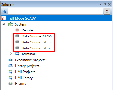
Assigning Data Source to the Terminal
After expanding the terminal by using the arrow to the left of the name and clicking on the terminal channel terminalChannel right click and then select Assign Device from the context menu.

A dialog box opens with a list of data sources (or PLCs) that are available in the IDE project. Mark the desired data sources and click OK to assign them to a terminal.

Creating a data point table and SCADA schema
Since the solution is created in full mode, before creating the table or schema, an HMI project must be created. Then, in this project the table and, if applicable, the schema can be created or copied from another solution.
When copying a table/schema from another solution it is necessary to remap variables!
1. Adding a new HMI project
To create a new HMI project, right-click on the HMI Projects row in the Report and select Add New HMI Project from the context menu.

Dialog box opens in which must be specified the name and location of the new HMI project. It is strongly recommended to keep the location in the project directory.

2. Creating a table/schema of data points
The data point table or schema is created by right-clicking on the HMI project and selecting Add new HMI template from the context menu and selecting the appropriate parameters.
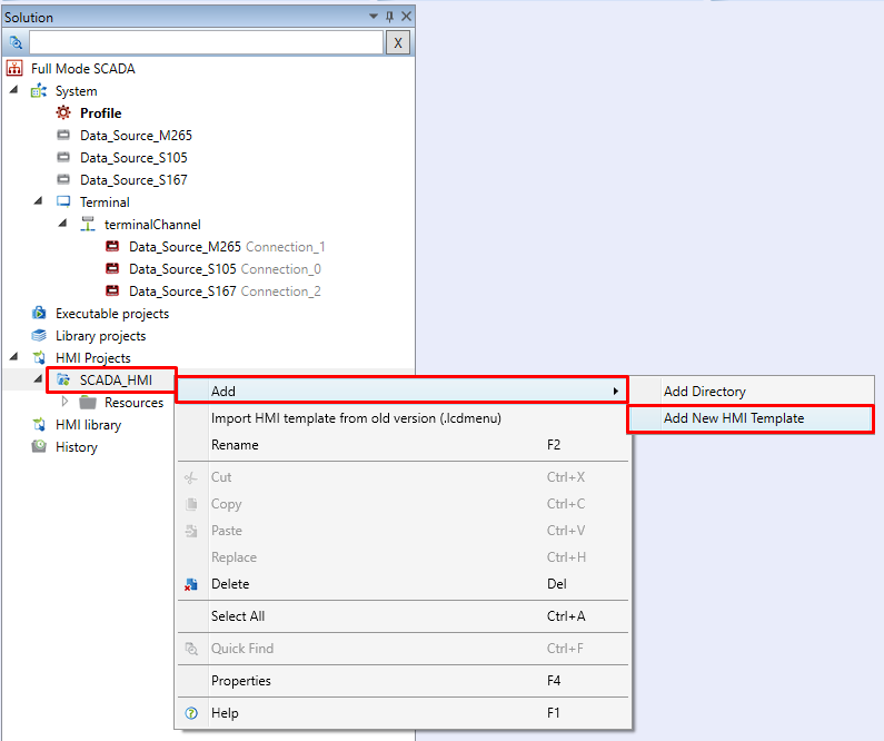
Setting up a table or schema and mapping data points is described in separate articles (table/schema).
3. Table and SCADA scheme assignment
After creation of table/schema, the templates must be assigned to a terminal. Click on the terminal to display its properties in the right column, where the items Data Point Table and Schemes are located. Data point table or schema created in the previous steps must be assigned to these items.

Outcome and risks
Extra care must be taken when making changes to the project, especially when making changes to individual data sources, where the .exs file will be changed and possible disconnection from the target PLC will occur. When update happens on a data source or project moves, it is necessary to compile the target project and then upload the updated SCADA definition in the Mervis SCADA web interface.
As a sample project, a simple report was created using three data sources representing Unipi PLCs from other solutions and a SCADA terminal with a data point table. The table contains three counter values, one from each PLC.
The resulting solution looks as follows:
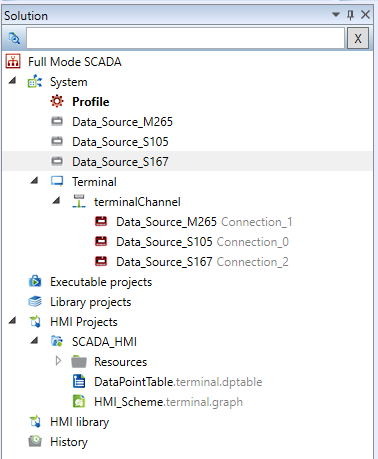
Data points table containing counters of individual PLCs:

The resulting appearance of the table in the SCADA interface:
