Controlling a PLC through SSCP protocol from another PLC
The SSCP protocol (Shark Slave Communication Protocol) is a proprietary communication protocol of Mervis systems. When compared to Modbus, SSCP holds the advantage of higher data transmission speed and support of secured communication. It serves for configuration, programming or data transfers. Data transfers are then the main focus of this tutorial - specifically, it demonstrates how to set up two PLC to allow one controller to control the other.
Patron
Neuron
Gate
Unipi 1.1
Axon
Prerequisites:
- Local network connectivity (any switch or router))
- 3× network cable (RJ45)
1 Basic project settings in Mervis IDE
Create a new project in Mervis IDE, or integrate into an already existing one. Follow the steps below:
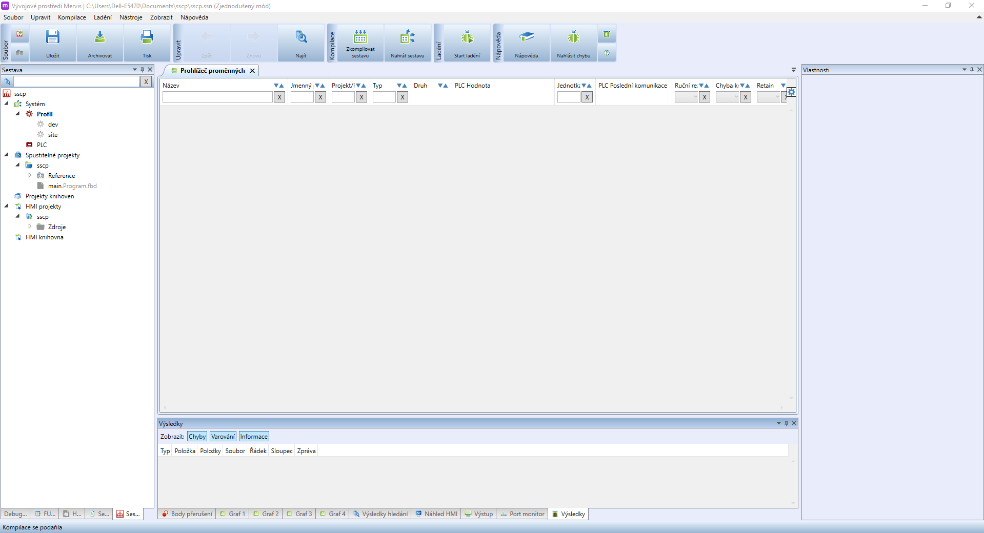
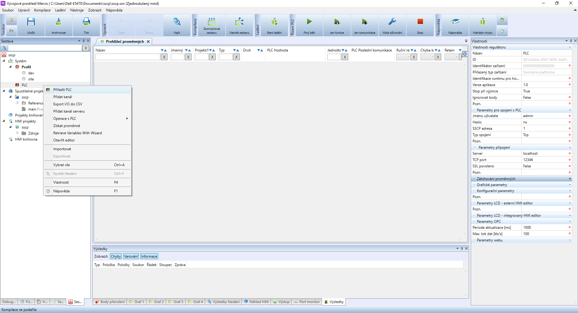
Create the project in Simple Mode and then switch it to Full Mode. Then connect the first PLC to the project by right-clicking on PLC and selecting Attach PLC.
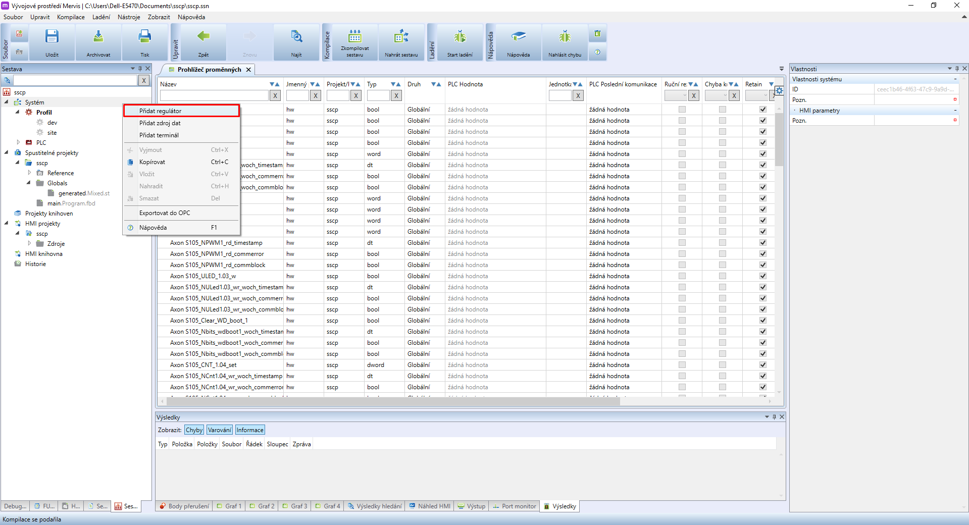
After that, connect the second PLC. Click on System and select Add Regulator.
For convenience, we recommend establishing a naming system.
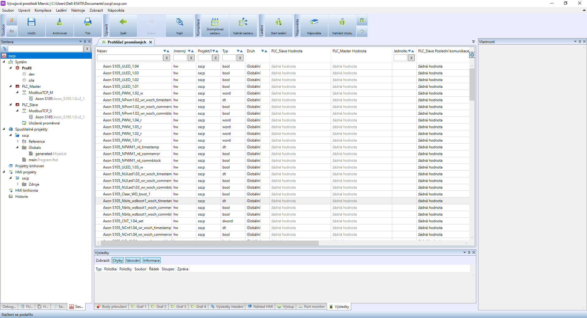
- name the first PLC as PLC_Master
- name the second PLC as PLC_Slave
- we recommend naming automatically created channels (channel, channel_0) as Modbus_TCP_m (master) and Modbus_TCP_s (slave)
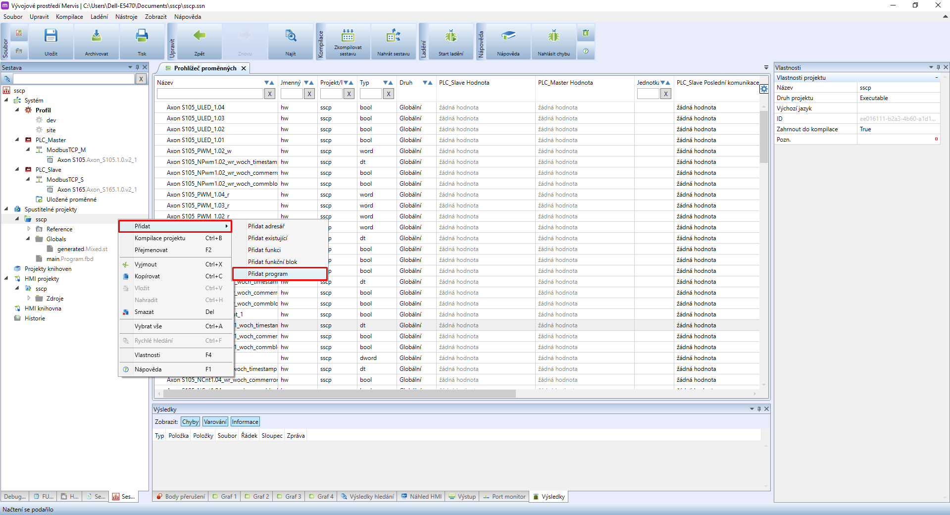
The next step is to create a program for PLC_Slave. Right-click on the project in the right panel, section Executable projects and select Add and Add program. (if you wish to create a program using function blocks, create program.fbd)
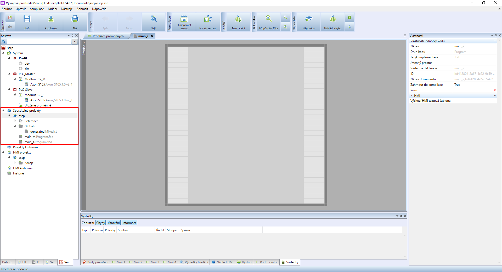
Name the program as main_s. Rename the main automatically generated program to main_m. The result should look like this:
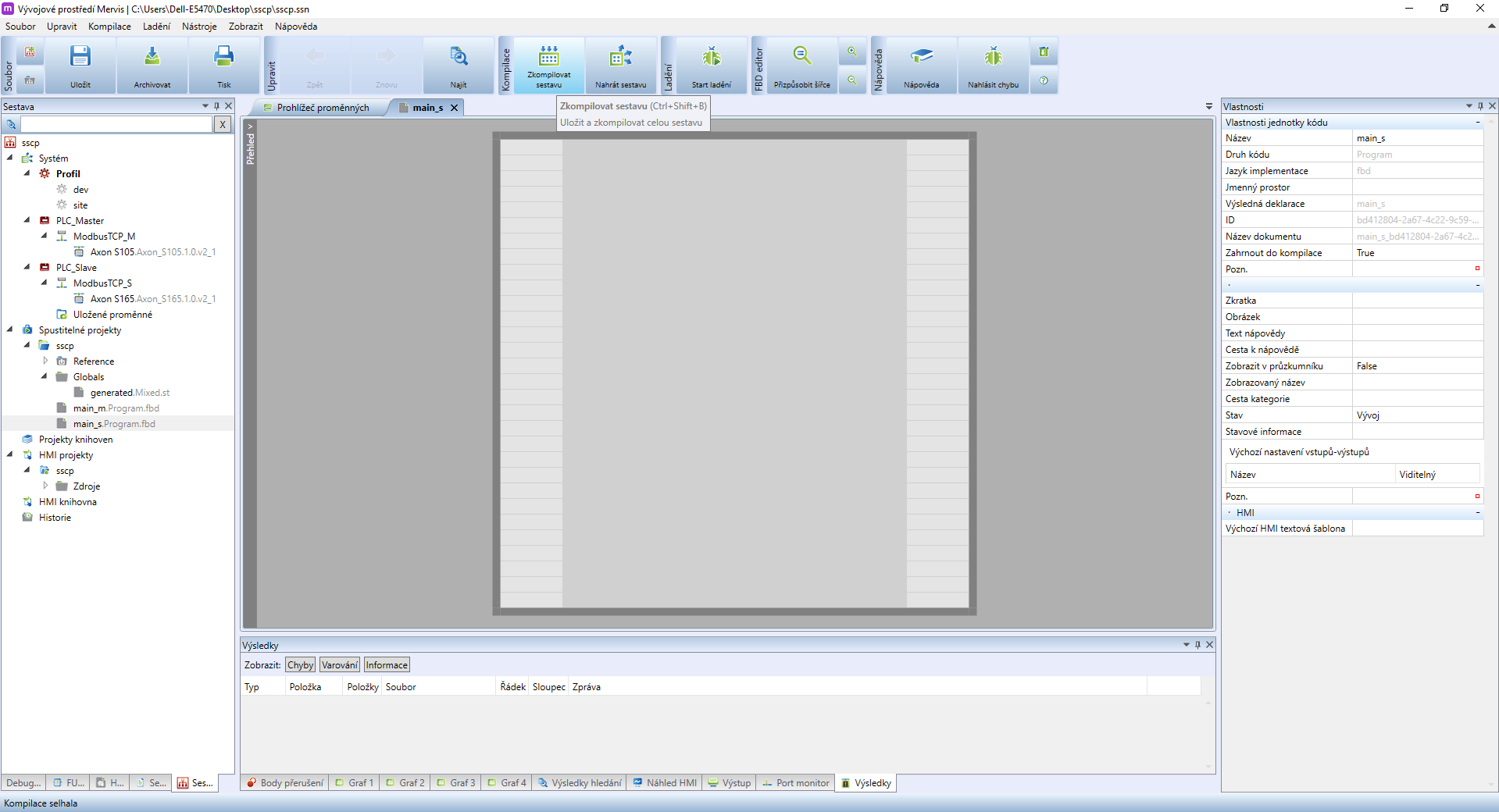
You now need to compile the project to perform all required changes in it. Mervis IDE may display a compilation error - ignore it and continue to the next step.
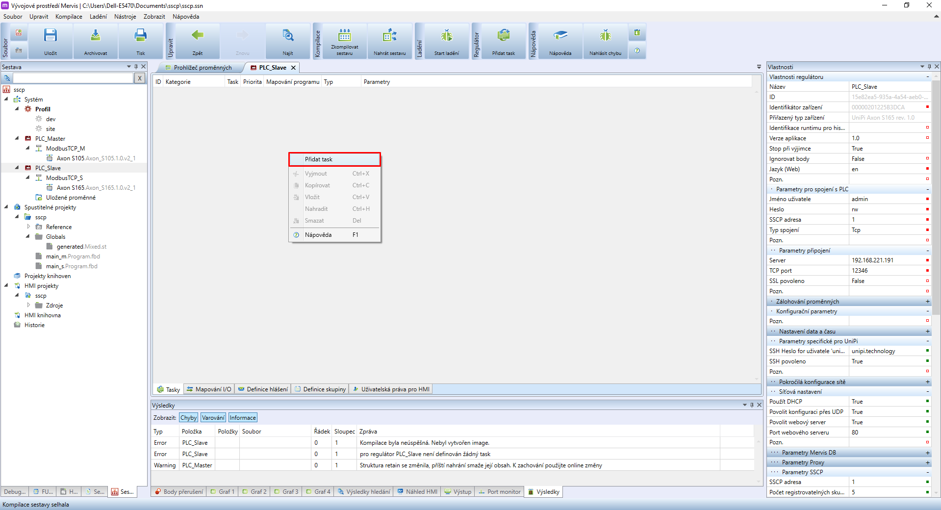
Double-click on PLC_Slave to open its properties. Right-click into the blank space to display a context menu, in which select Add Task.
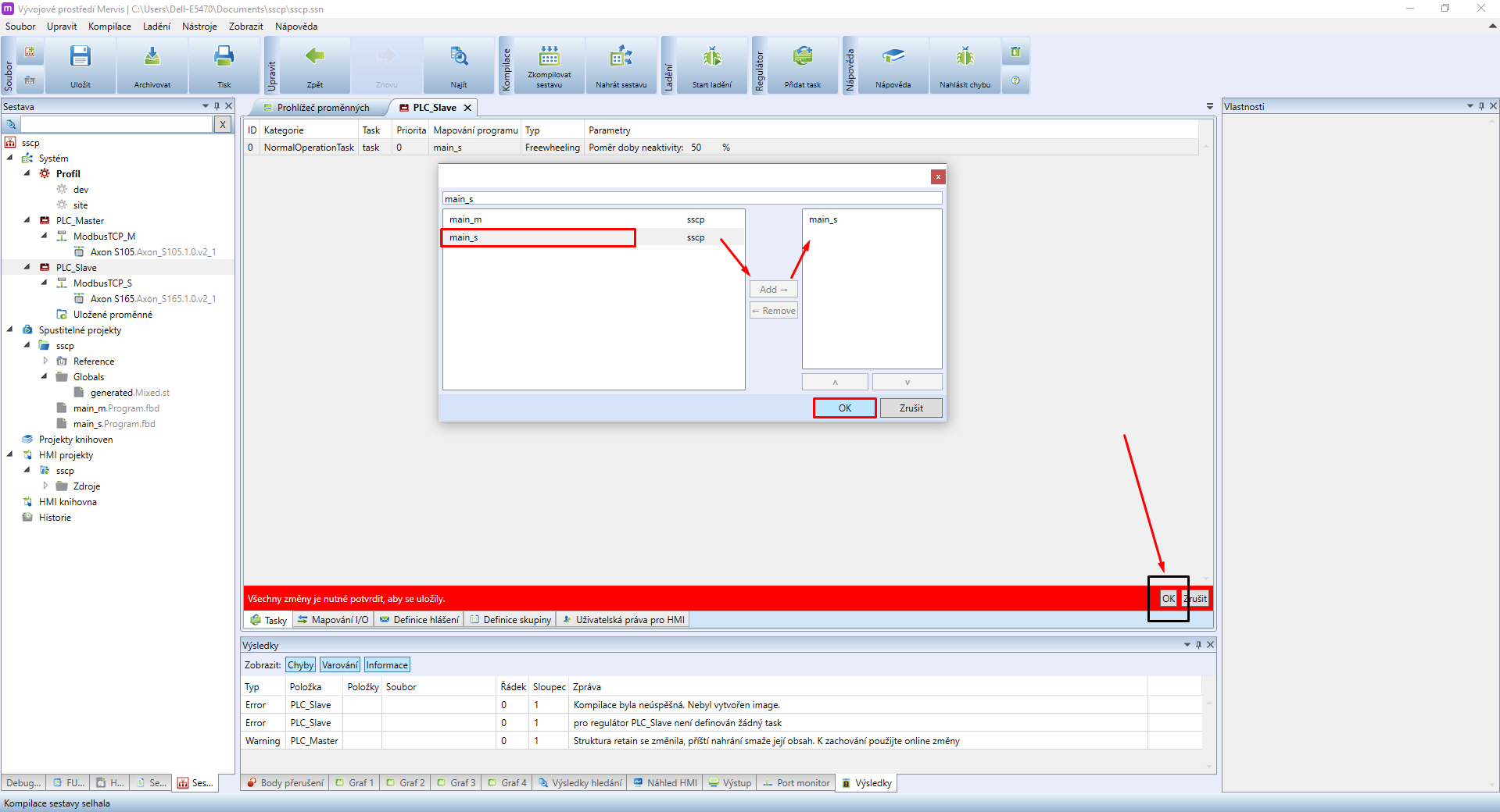
Now is the time to map the program into the new task tasku created in the previous step. Double-click in the blank space in the program mapping panel and attach main_s. Save the changes by clicking on OK in the red panel.
You can now create communication channels to connect additional devices
Examples are available in the following guides:
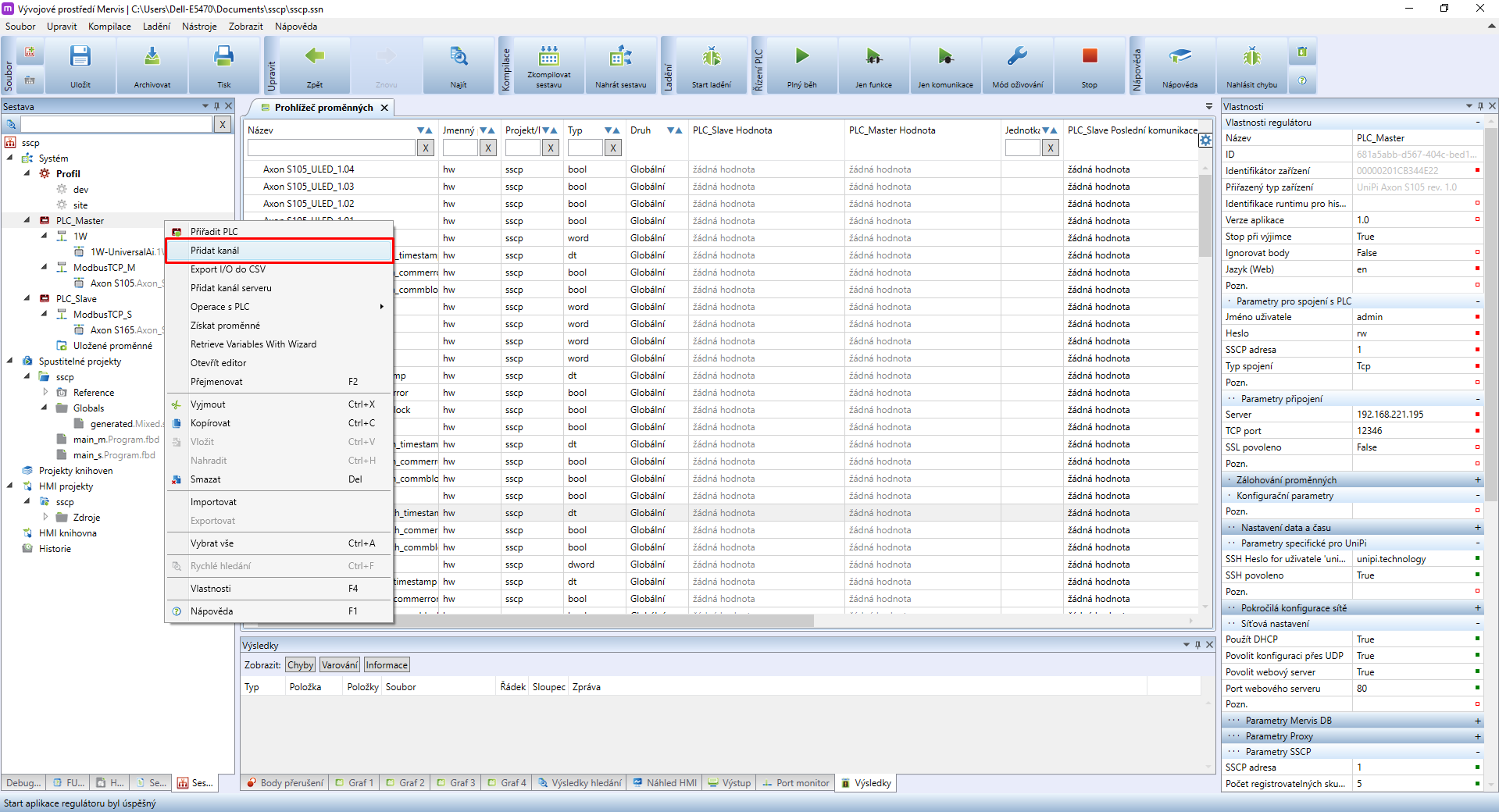
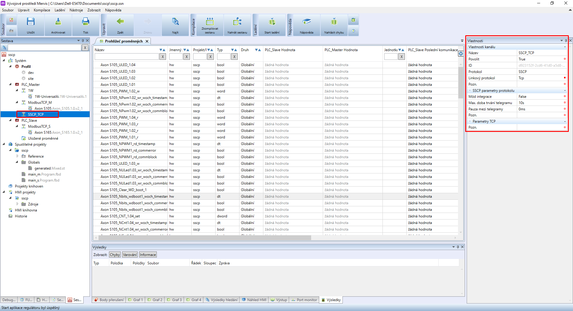
Once you have all the communication channels and their devices configured, create another communication channel and name it SSCP_TCP. In Properties set Protocol to SSCP.
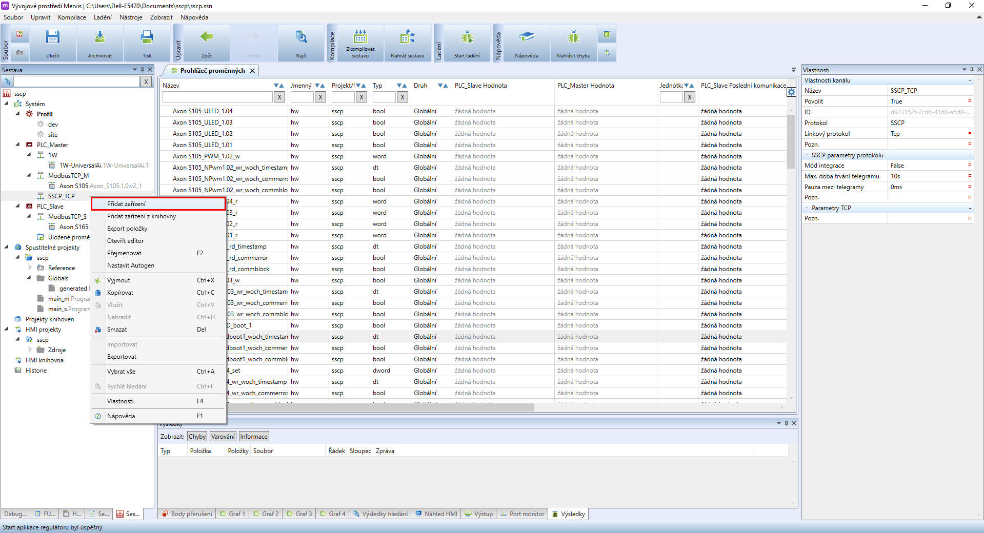
Right-click on the SSCP_TCP kanál and select Add device.
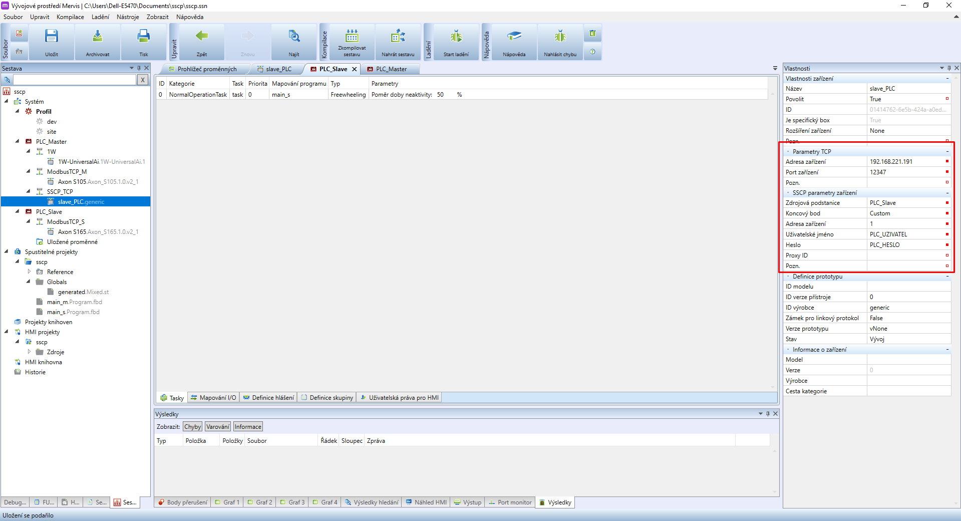
Name the device slave_PLC, select it and look into the right panel Properties. In SSCP device parameters you need to select Source substation and Custom endpoint. By doing so another configuration will be displayed. All necessary info can be found in PLC properties. For communication with the local network enter the following parameters:
Parametry TCP:
- Device address: Enter the IP address/domain
- Device port: 12346
SSCP device parameters:
- Device address: enter the SSCP device address
- User name: PLC user name (at least single Full control)
- Password: PLC user password
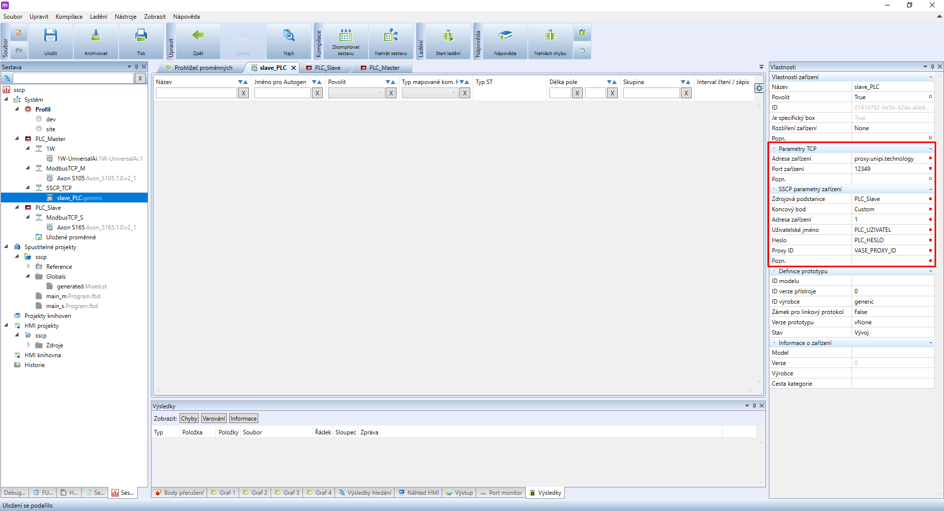
It is also possible for two PLCs to communicate through SSCP over vast distances. In this case, you also need to configure proxy on PLC_Slave.
If you want to use the proxy and it is already configured on the said PLC, adjust the following paramaters of the SSCP_TCP channel:
TCP Parameters:
- Device address: proxy.unipi.technology
- Port device: 12348
SSCP Device Parameters:
- Proxy ID: vaše unikátní Proxy ID from the Unipi customer account
Proxy connection variant is not recommended for control. It is, however, useful for collecting data (ie. temperatures) from multiple controllers into a single PLC for further use.
2 Variables, mapping, couples
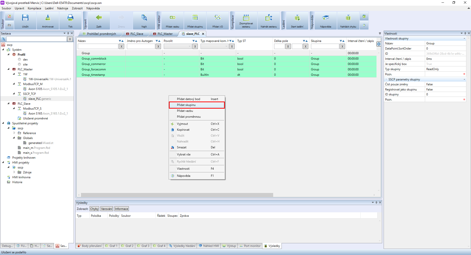
Create two groups in the SSCP device - a read group and a write group. Name those groups accordingly: Read_group, Write_group. These groups serve for reading or writing into several data points. For a low number of data points these two groups are sufficient. For larger projects or for transferring a larger number of data points we recommend dividing the group into several smaller groups - this applies especially to write groups for PLC_Slave.
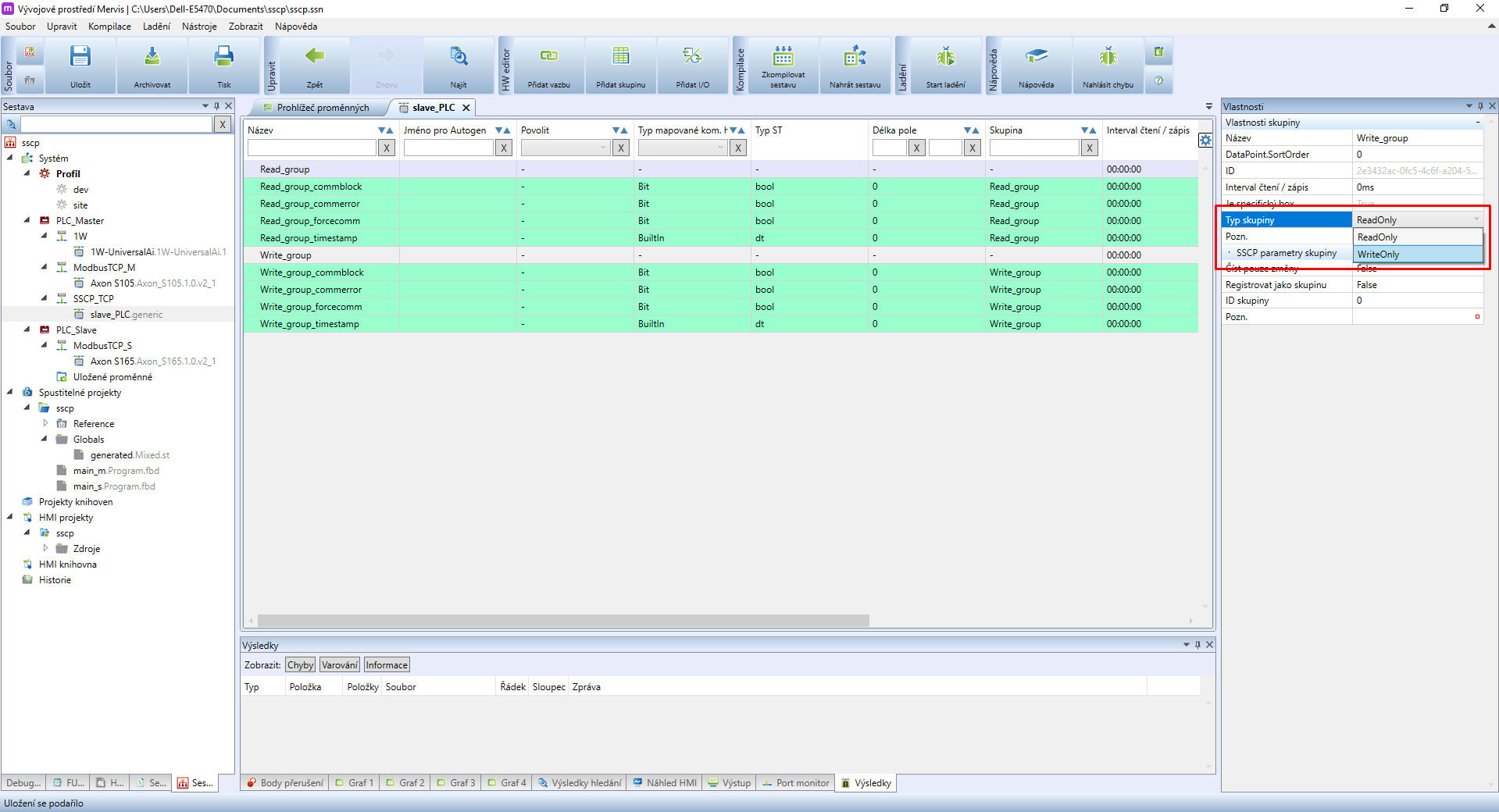
In the Write_group properties you need to set the Group type tp WriteOnly
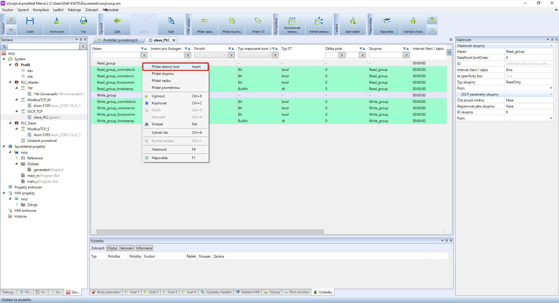
Right-click somewhere in the SSCP device space and add two data points.
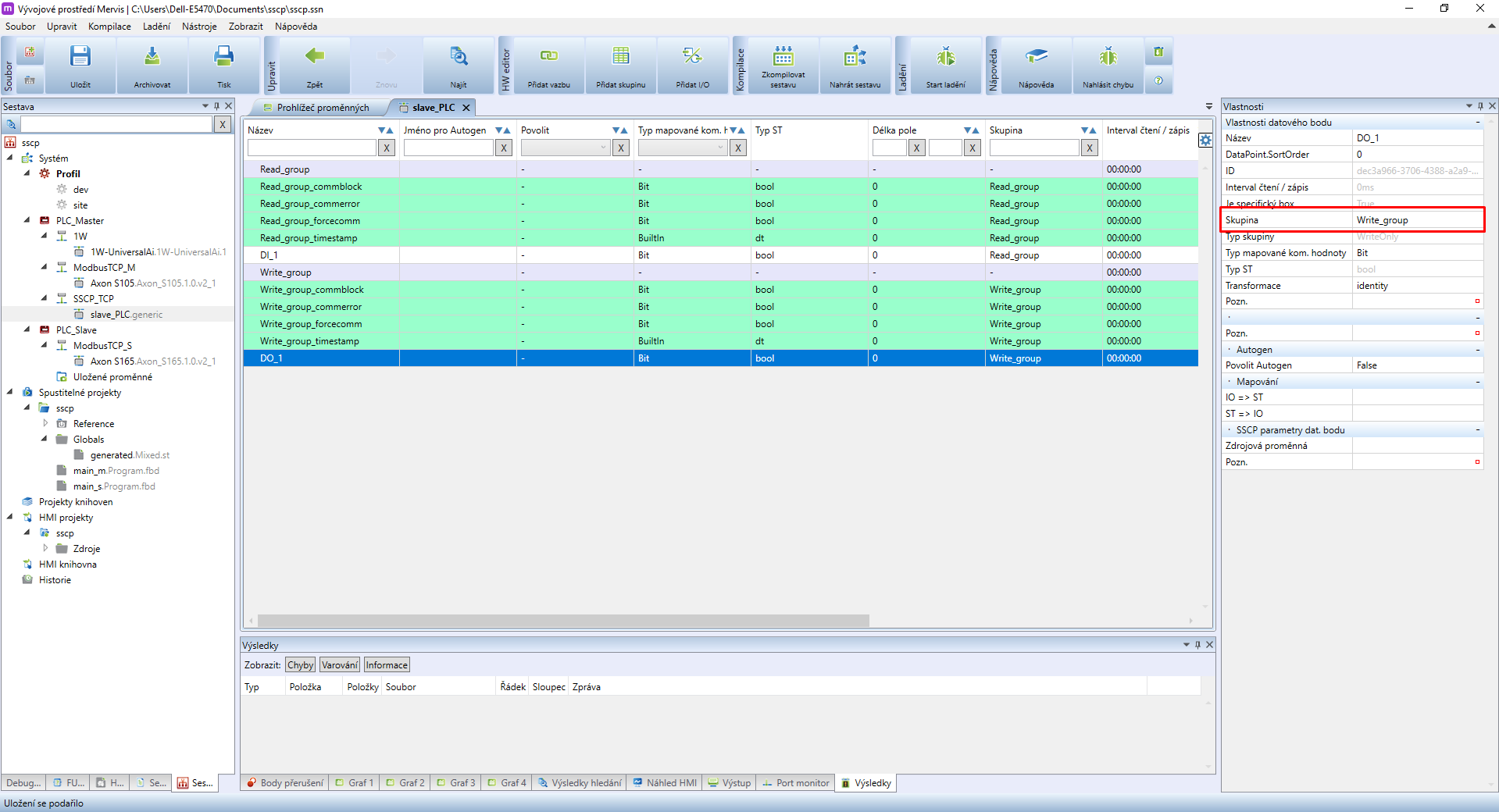
Upon selecting a data point its properties will be displayed in the right panel. Assign one data point to the Read_group and the second to the Write_group. Name both according to their use. For this tutorial name those data points DI_1 and DO_1.
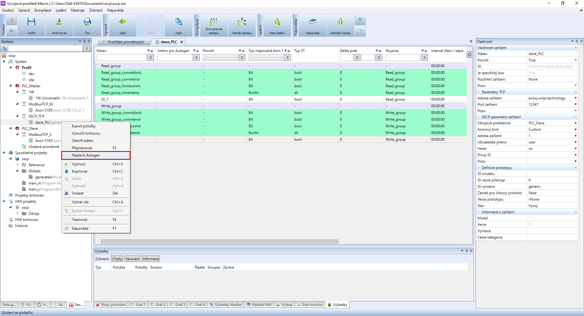
The next step is to use Autogen, to create variables for data points. Right-click on each device for each channel and select set Autogen. More info about Autogen is availabl here.
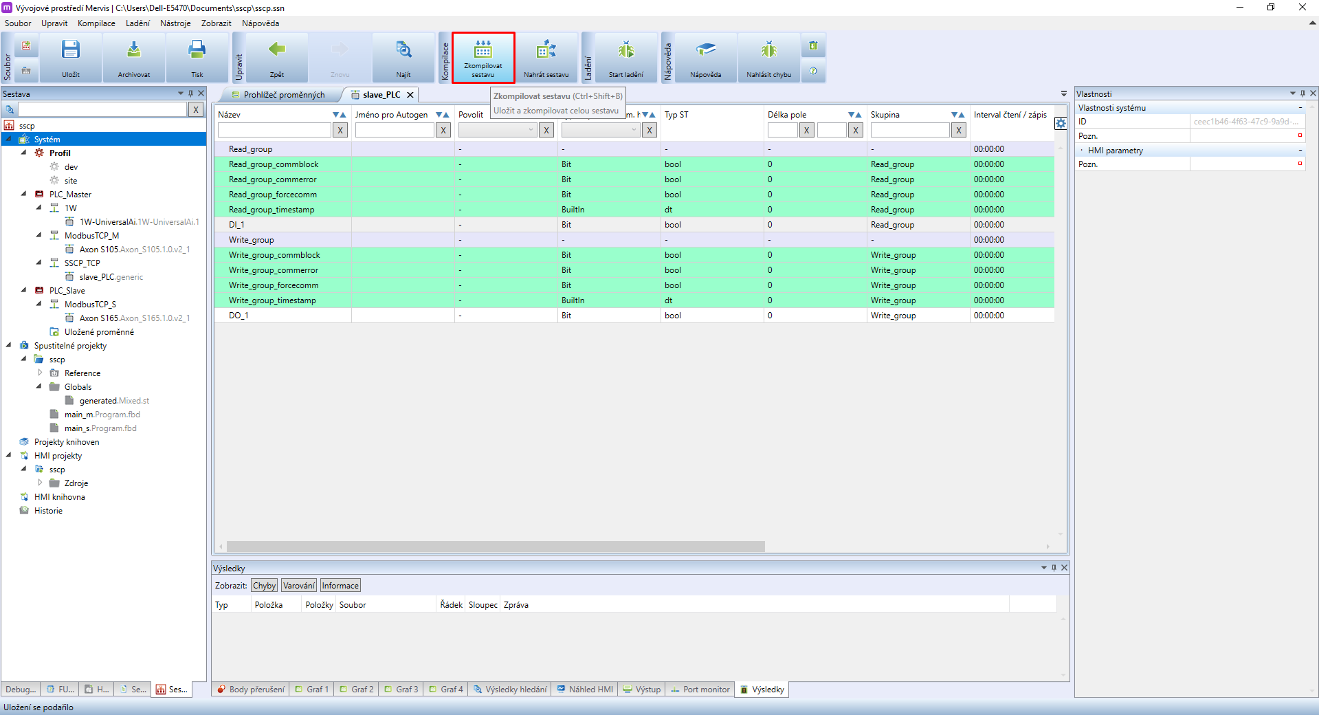
After creating the variables via Autogen it is necessary to Compile Solution. Mervis IDE may again display compilation error - again, ignore it and continue to the next step.
It is now necessary to insert source variables for each data pointin SSCP_TCP channel devices. Double-click on slave_PLC to open a list of its data points. In the right panel data point properties will be displayed. Look for SSCP Data Point Parameters, specifically for the source variable tab, and click on this symbol:  .
.
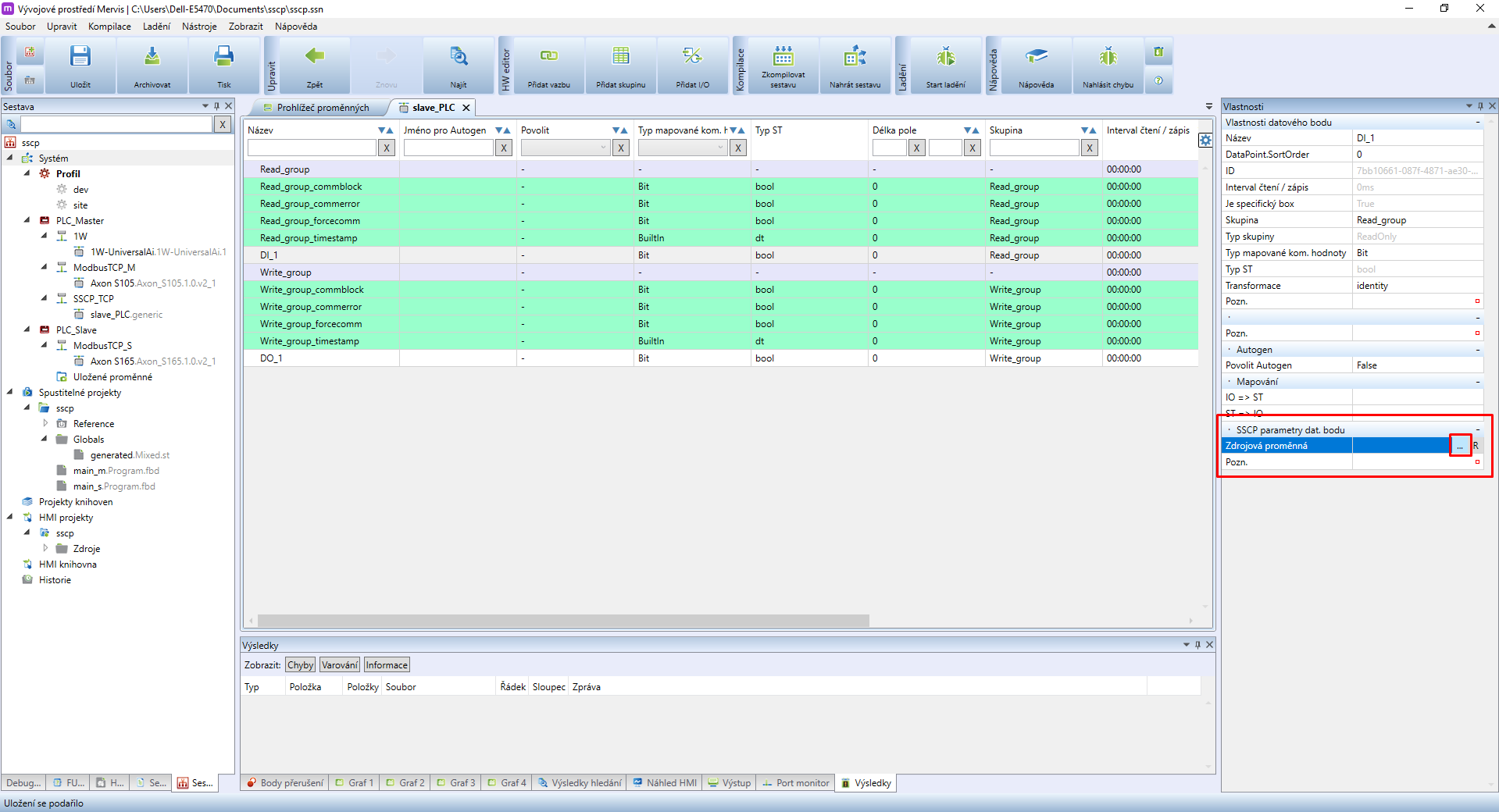
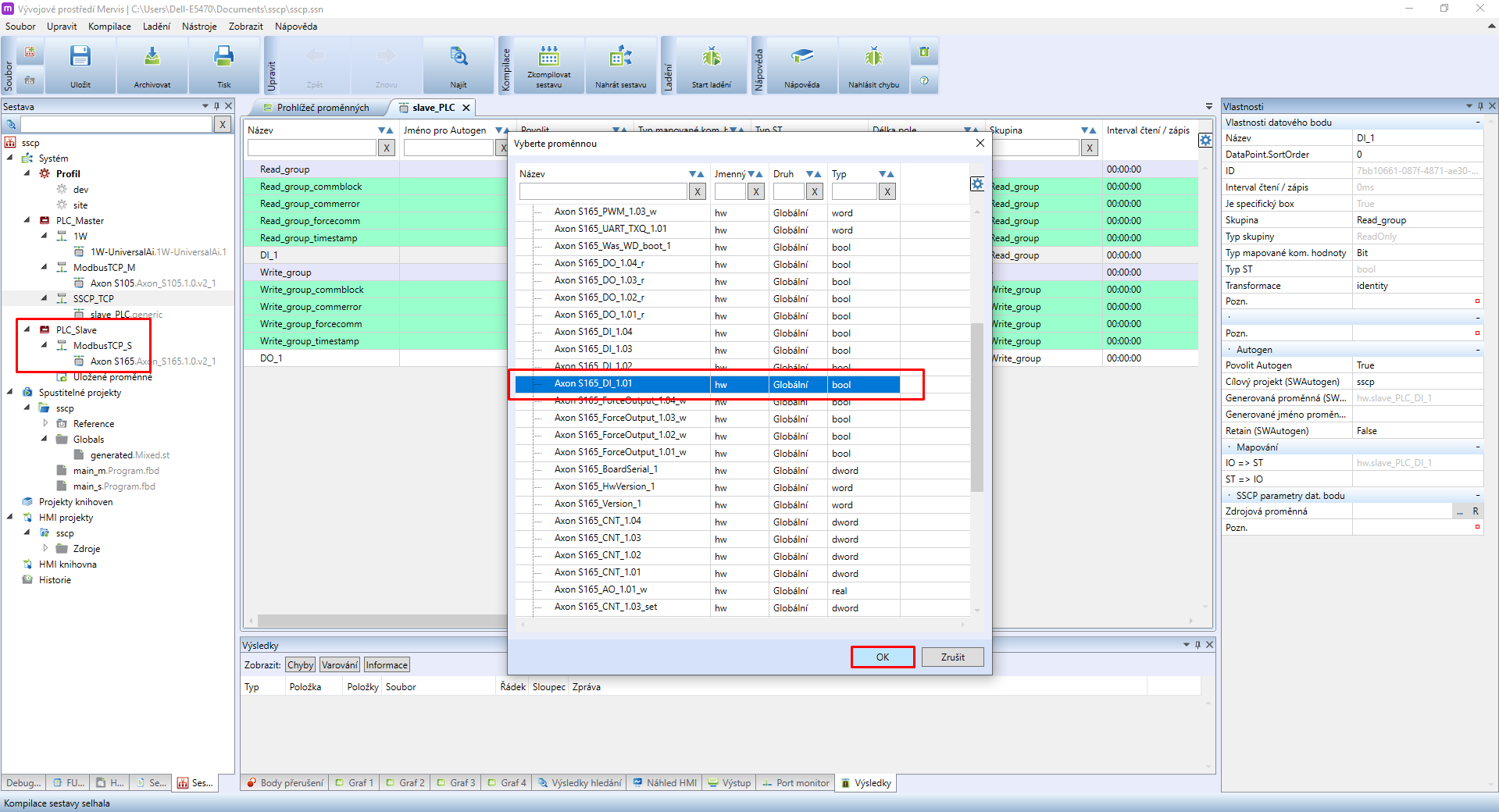
For DI_1 we need to find DI_1.01 variable from PLC_Slave.
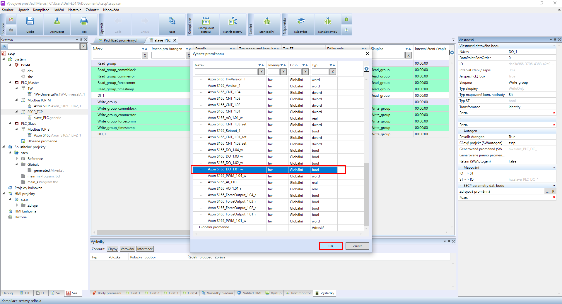
Repeat the same method for data point DO_1. The only difference here is setting up DO_1.01_w as the source variable.
SSCP device configuration is now completed. You can use the variables in your main_m program on PLC_Master.
3 Variable usage (main_m)
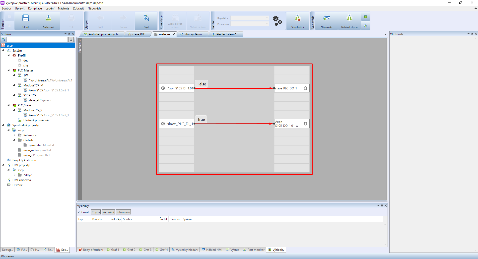
Insert the newly created variables into the main_m program running on (PLC_Master). Read data points from PLC_Slave (DI_1) should be added to the left panel for input variables. The right side is then reserved for data points for writing into PLC_Slave (DO_1).
To test the functionality, you can look into Variable browser or you can connect the PLC_Slave input to the PLC_Master output and vice versa:
- add the DI_1 (PLC_Slave) variable as input (left), the DO_1.01_w (PLC_Master) variable as an output (right) and connect them.
- add the DI_1.01 (PLC_Master) as an input (left), the DO_1 (PLC_Slave) as an output (right) and connect them.
Upon finishing the configuration Deploy Solution
4 Result
- Everything is now set and both PLCs react to the DI_1.01 input by writing their values to DO_1.01 of the second PLC.
- All configurations and settings of the control logic are performed on PLC_Master
- PLC_Slave can simultaneously execute its program. In this guide, however, PLC_Slave acts only as an external module.
- Using this method it is also possible to transfer program variables, ie. for collecting data from temperature sensors.