1-Wire
1-Wire is a name for a communication bus designed by Dallas Semiconductor company, that is designed for the low-speed transmission of digital signals. As the name suggests 1-Wire sensors can theoretically use only a single conductor for both power voltage and data. The negative pole can be grounded. In practice, however, at least two conductors are used → 1W (DATA) and GND. 1-Wire sensors from the Unipi product range use four conductors (VCC, ![]() 1W,
1W, ![]() 1W, GND) for better reliability and enhanced serialisation options.
1W, GND) for better reliability and enhanced serialisation options.
A distinct advantage of the 1-Wire bus is the low component price; thermometers available at Unipi e-shop are offered from approx. € 10 apiece. Up to 15 sensors can be connected to the bus, OR a distance of up to 200 m from the controller can be reached (with a lower number of sensors). Each sensor is also provided with its own HW address for its addressing on the bus.
1-Wire temperature sensor
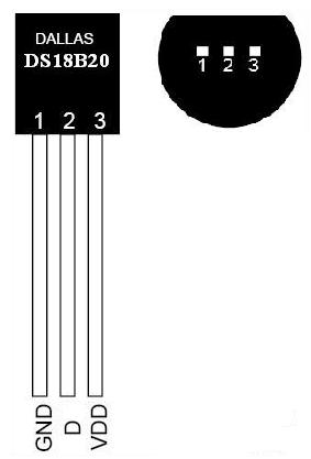 The DS18B20 is widely used 1-Wire temperature sensor placed within TO-92 casing.
- power voltage range: 3.0-5.5 V⎓
- measurement range: -55 °C / +125 °C
- accuracy ±0,5°C in the range of -10 °C / +85 °C
- conversion of 12-bit temperature value to a digital signal (750 ms max. latency)
- can be powered by the 1W (DATA) wire - parasite mode
1-Wire devices offered by Unipi
- Unipi Extension xG18 - Modbus/RS485 extension for up to temperature sensors.
Installation recommendations
Mind the EM interference
The 1-Wire bus is prone to electromagnetic interference, it is thus recommended to use a shielded cable J-Y(ST)Y (0.8 mm) with a pair of twisted pairs, or FTP CAT6 cable. The cable must be routed through places with the least interference possible and must be well clear of any cables supplying induction loads. The most frequent sources of interference are frequency converters, inverters etc.
Follow the correct
It is also important to follow the bus topology and to avoid creating any branches. To meet this condition we recommend using Unipi 1-Wire thermometers featuring a pair of data conductors - one leading back to the PLC or the previous sensor on the bus, one leading to the following sensor in the line. On the end of the bus, a sensor must be placed to avoid any signal bounces.
Mind the limitations
Communication speed is pre-defined, eg. cannot be decreased to mitigate the interference as with the RS485 interface. Any issues with the bus should be fixed only by adjusting the wiring, decreasing the number of sensors or dividing the network between multiple controllers. To prevent such issues, we also developed the Unipi Extension xG18 - a Modbus RTU extension module with eight 1-Wire ports.
Use the 1-Wire only in suitable installations
Given the sensitivity towards EM interference, it is not recommended to use the 1-Wire in industrial automation. Its low cost, simplicity and wide range of compatible products makes the bus an ideal solution for smart home applications, especially when combined with the versatility and broad connectivity of Unipi controllers.
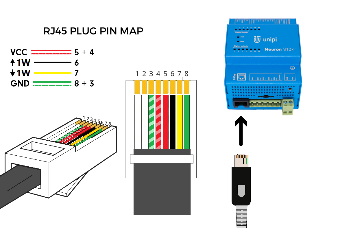
RJ45 connector connection for Unipi 1-Wire
The RJ45 connector is useful especially in the following cases:
- you need to connect a pair of sensors to a Unipi Neuron or Unipi Axon controller using the 2-port splitter
- you need to connect one sensor to the Unipi Neuron controller with an older 1-Wire RJ45 connector
- you need to connect multiple sensors using the 8-port

A total of 4 wires is used. However, the connector description above has 6 wires connected, as the VCC (or +5 V⎓) and GND voltage conductors can be doubled (depicted by white streaks in the picture). As some devices were not designed for a dual power supply we need to connect the pins 5 and 8 (basic colours) first.
| Pin (contact) number | Meaning |
|---|---|
| 1, 2 | unused |
| 3 | GND |
| 4 | VCC (+5 V⎓) |
| 5 | VCC (+5 V⎓) |
| 6 | |
| 7 | |
| 8 | GND |
The picture below shows a (basic) wiring used for the Unipi temperature sensor:

Note: ![]() 1W, sometimes also DATA_0, is the main data wire. That said, if you connect a cable sensor with only a single data wire to the RJ45 connector, always connect it to pin 7 (eg.
1W, sometimes also DATA_0, is the main data wire. That said, if you connect a cable sensor with only a single data wire to the RJ45 connector, always connect it to pin 7 (eg. ![]() 1W pin). The
1W pin). The ![]() 1W contact, sometimes also DATA_1, is a supplemental contact of Unipi sensors designed for a maximum possible bus serialization and serves for connecting the next sensor on the bus. The Unipi 1-Wire hub can serve as an example of the double-data wire principle. If you use a non-Unipi cable sensor with only a single data wire, the above-mentioned serialization with Unipi 1-Wire hub is not possible. You can, however, connect the sensor to the end of the bus (eg. as the last sensor in the hub).
1W contact, sometimes also DATA_1, is a supplemental contact of Unipi sensors designed for a maximum possible bus serialization and serves for connecting the next sensor on the bus. The Unipi 1-Wire hub can serve as an example of the double-data wire principle. If you use a non-Unipi cable sensor with only a single data wire, the above-mentioned serialization with Unipi 1-Wire hub is not possible. You can, however, connect the sensor to the end of the bus (eg. as the last sensor in the hub).
The Unipi Unipi Extension xG18 module allows an easy connection of multiple temperature sensors using a single data wire, with each sensor having its own channel (connector). Connecting multiple sensors to a single channel is not possible.
1-Wire bus on Unipi devices
By default, Unipi 1.1 board, all Neuron controllers and most of Patron or Axon controllers feature a single 1-Wire bus port. In the Unipi product range, you can also find a range of 1-Wire sensors for measuring various quantities. Alternatively, you can use 1-Wire sensors outside the Unipi product range.
Older variants of Unipi Neuron controllers feature an RJ45 1-Wire port (made in black to distinguish it from the ETH connector). the older RJ45 1-Wire connector

Unipi 1.1/1.1 Lite are also provided with RJ45-type 1-Wire connector, allowing you to easily connect 1-Wire sensors with RJ45 connector.
Unipi Patron, Axon and newer Unipi Neuron version feature a three-wire terminal replacing the RJ45 connector for improved reliability- new 1-Wire connector
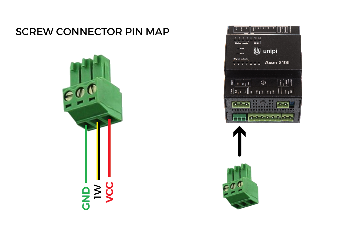
If you wish to connect a sensor to a controller with the 3-pin terminal, you can do so by three methods:
- cut off the RJ45 connector from the sensor and connect to the three-wire 1-Wire terminal on the controllers
- use a cable reduction in combination with the Unipi 1-Wire hub
- use the 1-Wire splitter (3-pin terminal variant)
All described methods are depicted in the schematics below.
The sensor features a 4-wire connection to improve the reliability of branched networks. However, it is possible to modify it for 3-wire connection by joining 1W (DATA) wires if needed.
You can also short-circuit VCC and GND wires to run the sensor in parasite mode with communication through two wires.
Connecting a single 1-Wire sensor to the Unipi controller
The 1-Wire thermometer can be connected to a 3-pin screw terminal after a simple modification of its connector
- cut off the RJ45 connector
- fasten ferrules onto the conductors
- screw the conductors into the plug-in screw terminal according to the picture below (the plug-in terminal is included in the controller's package)

Connecting a pair of 1-Wire sensors to the Unipi controller via RJ45 splitter
No modification of the thermometer itself is needed to connect two thermometers to a single controller. All you need to do is to purchase a corresponding variant of the 2-port 1-Wire splitter featuring a pair of RJ45 ports; the splitter is available in both connector variants (RJ45 / 3-pin screw terminal)

Connecting multiple 1-Wire sensors through a 1-Wire hub
A compact 8-port 1-Wire hub features eight RJ45 ports and allows you to connect multiple 1-Wire thermometers or other sensors with the RJ45 connector. To connect the hub to a controller you can either use a suitable patch cord (on controllers with the RJ45 port) or the cable reduction (on controllers with the newer 3-pin screw terminal).
It is necessary to follow the correct port order when connecting devices to the hub! Port 1 must be always used as an input port, the remaining ports must not be skipped; otherwise, any devices connected after the skipped port would be cut off from the 1-Wire bus.

Creating a multi-hub extensive network of 1-Wire sensors
It is possible to create a chain of multiple hubs if an extensive network of 1-Wire sensors or devices is needed. When interconnecting two hubs the topology stays the same - Port 1 serves as an input while the output is located on the last port in order.
Any other 1-Wire device connected after the output port will be cut off from the bus!

Description of Unipi 1-Wire sensors
The basic 1-Wire temperature sensor is described above in the RJ45 connection chapter.
1W-T/H-IB, 1W-T/H-IB2, SD 115C & SD 125C
Unipi product range also contains 1W-T/H-IB and 1W-T/H-IB2 compact on-wall sensors designed for measuring temperature (1W-T-IB2 model), or temperature and relative air humidity (1W-TH-IB2 model) in building interiors. Furthermore, the exterior wall sensor SD 115C, or the sensor SD 125C for measuring the temperature of water or air in pipes or tanks. Sensors are equipped with 4-wire screw or spring terminals and can be modified for RJ45 connector or for the 3-wire terminal.
Three-wire terminal connection
This option is suitable for cases when you need to connect single sensor to Unipi controller equipped with the 3-pin terminal, or you plan to add more sensors behind the first one.

RJ45 connection
Connection to RJ45-connector network cable is useful for star-shaped network topologies created from 1-Wire hubs. You can also use it to connect the sensor to Unipi 1.1 extension board, or to the older variants of Unipi Neuron controllers.
All sensors with the DS18b20 chip and parasite power support can also be connected to the Unipi Extension xG18 module.. Coloured connection scheme on the picture corresponds to the T568B connection.
