This is an old revision of the document!
Connecting to Unipi extension
The Unipi extensions are a convenient way how to extend the number of inputs and outputs at one location or make accessible at another one.
The communication between controller and extension is via RS485 ports. The extension acts as a Modbus slave, which has extended support in the Mervis.
HW connection
You need only two cables (e.g. JYSTY 2×0.8) to connect the Unipi extension to the controller. Just interconnect the RS485-A port on the controller to RS485-A port on the extension and RS485-B on the controller to RS485-B on the extension.

For communication to work, you have to have identical serial port parameters on both sides - speed, data bits, stop bits and parity. Also, each extension unit has to have unique Modbus address. You can set those in two ways: by HW DIP switches or in the Mervis.
DIP switches
DIP switches are small levers with two positions - up or down. If the lever is pushed down, its specific function is enabled.

On all Extension models, the DIP switches allow for configuring bitrate, parity and address.
The RS485-END, placed next to RS-485 connectors, is intended for attaching or unattaching an internal 120Ω resistor between RS485-A and RS485-B ports for a proper termination of the RS-485 bus. The resistor needs to be attached if the said module is the last device on the bus - this instruction applies mostly for large serial buses several hundred meters long.
Switches 1 to 3 serve for device addressing in a binary format, and can be used to set an address within 0-7 range.
| Address | DIP no.1 | DIP no. 2 | DIP no. 3 |
|---|---|---|---|
| 0 | OFF | OFF | OFF |
| 1 | ON | OFF | OFF |
| 2 | OFF | ON | OFF |
| 3 | ON | ON | OFF |
| 4 | OFF | OFF | ON |
| 5 | ON | OFF | ON |
| 6 | OFF | ON | ON |
| 7 | ON | ON | ON |
DIP switch 4 configures the serial bus' bitrate. There are two bitrates available - 19200 bps (OFF position) and 9600 bps (ON position.
DIP switch 5 serves for switching between even parity (OFF position) or no parity (ON position).
Software settings
The connection parameters can be also set in Mervis. The HW settings take precedence, so to SW settings take place you have to set the address to 0. The rest will be described later in this tutorial.
Using UniPi extension in the Mervis
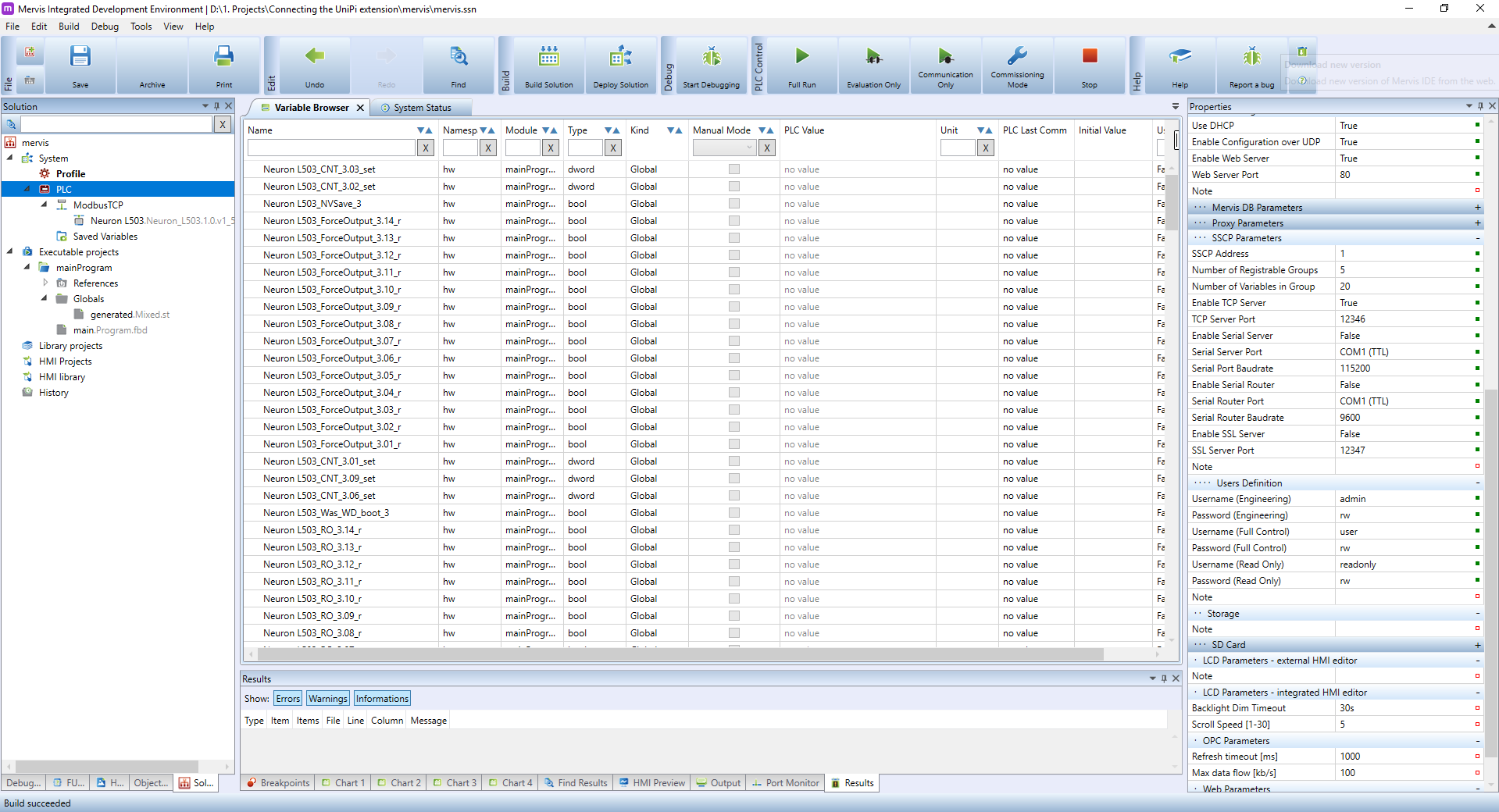
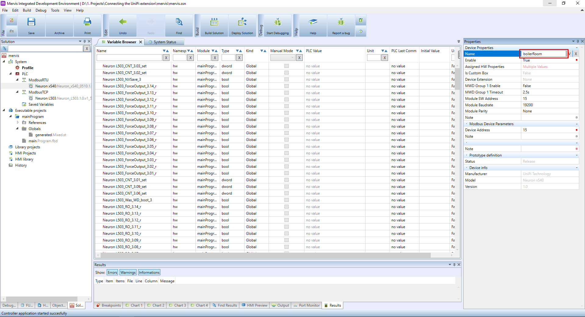
Let's assume you have a basic project in Full mode, you are attached to the controller, you have Executable project with one FBD program and this program is configured as a sole Task of the PLC. And you Set Autogen on the UniPi device. Your workspace should look like this:
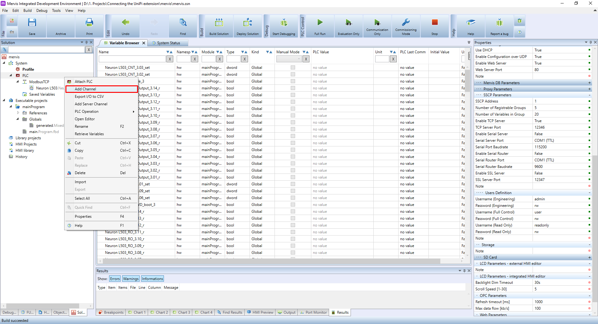
As we stated previously, the communication with Unipi extension is via Modbus RTU. To create a channel by right-clicking on the PLC in the Left panel and selecting the Add Channel option.
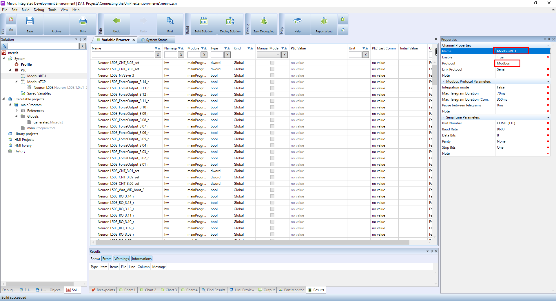
A new channel will appear under the PLC. Select it and in the Properties panel change the Name to something more descriptive, like ModbusRTU. Also, change the Protocol to Modbus.
Leave the Link Protocol to Serial, but change the Port Number to the serial port on your PLC. Our testing Unipi Neuron L503 is equipped with two RS485 ports, and we will use the one on the 1st group.
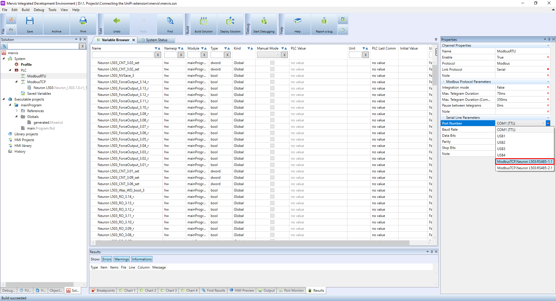
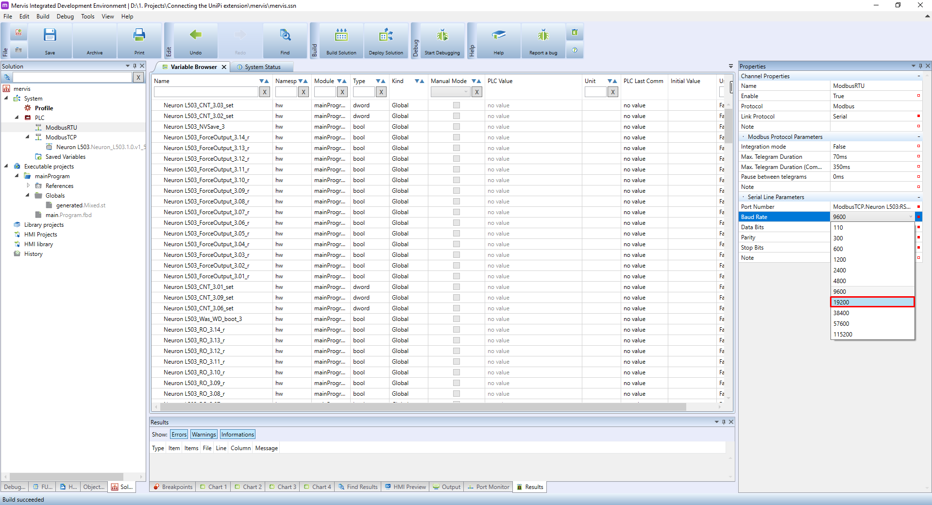
We will also change the Baud Rate (a.k.a speed) to 19200, as it is a default value for Unipi's extensions.
Now we can add the device and we can do it in two ways. You are used to right-clicking on the channel name and then clicking on the Add Library Device and then selecting the proper device from the list. This will work, but with Unipi extensions, you can let the Mervis detect all the units on the bus automatically and add all of them at once.
When a new channel is added, the autodetection will not work until you deploy the solution, because the PLC doesn't know this channel yet.
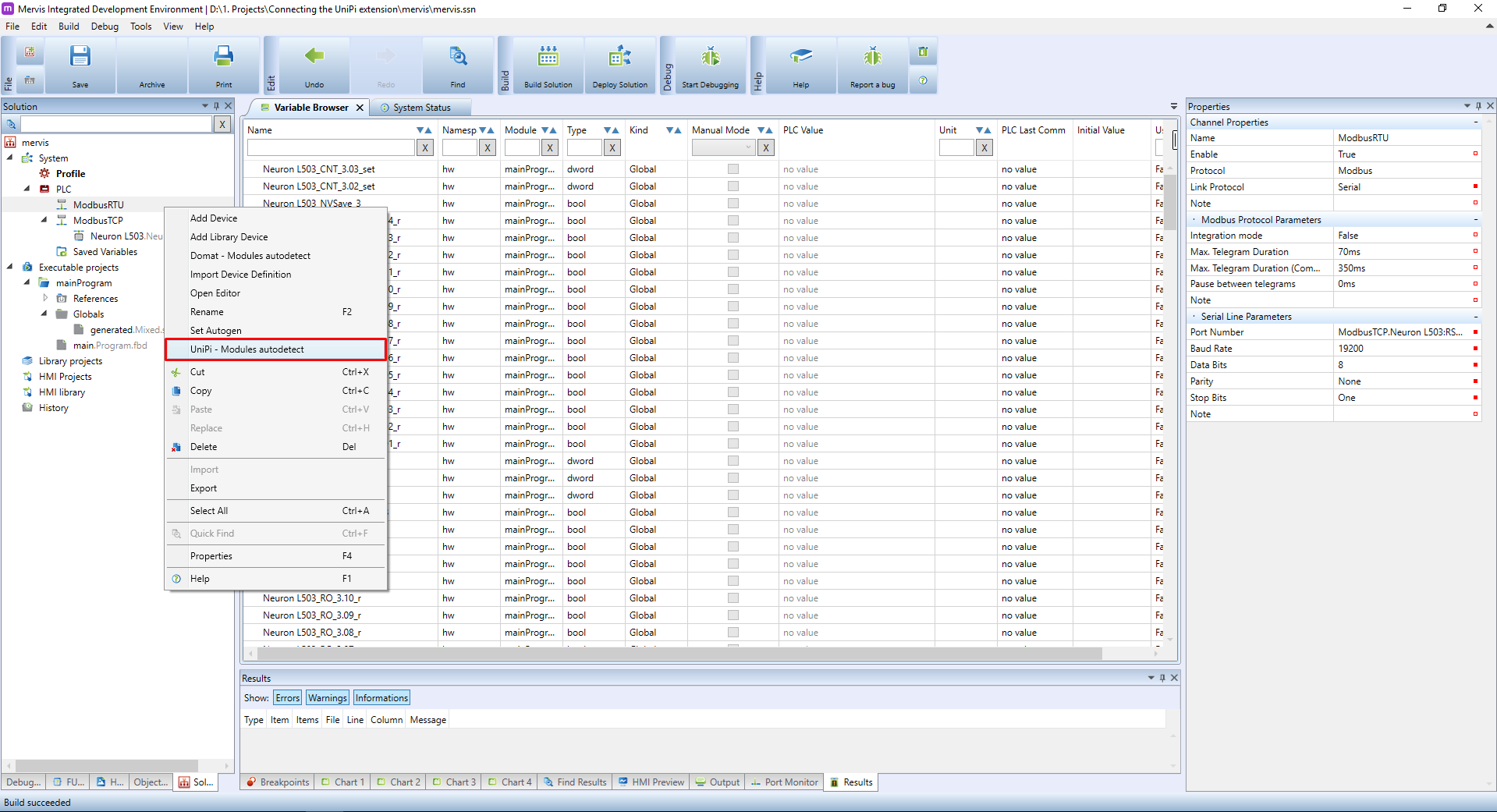
To autodetect the devices, right-click on the channel name in Left panel and in the context menu click on the UniPi - Modules autodetect.
You will be probably presented with dialogue warning you, that the autodetection needs to be executed while the PLC is in the Commissioning mode. The Mervis will offer you to switch to this mode and after the detection, it will switch back to the previous model.

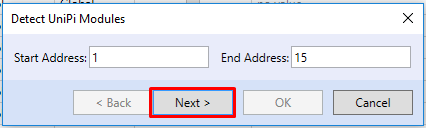
Next dialogue will ask you for the range of Modbus ID's the autodetect will look for. You can leave the default 1 - 15.
The detection has finished and you can see a list of Unipi extensions on your RS485 bus. You can tick the Import checkbox and import their definitions.

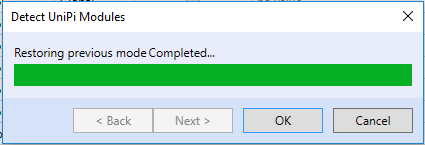
And confirm the restore to the previous mode.
A new device(s) will appear under the channel. You should rename them to something more descriptive, e.g. by their purpose or location.
Also, run Set Autogen on the device to generate all the variables which the extension has.
Turn on the Debugging and select the Variable browser tab in the Main window. Under the name, search for the name you gave the extension (in our case the boilerRoom). In the browser, you should now see only the variables for the extension and their current values.
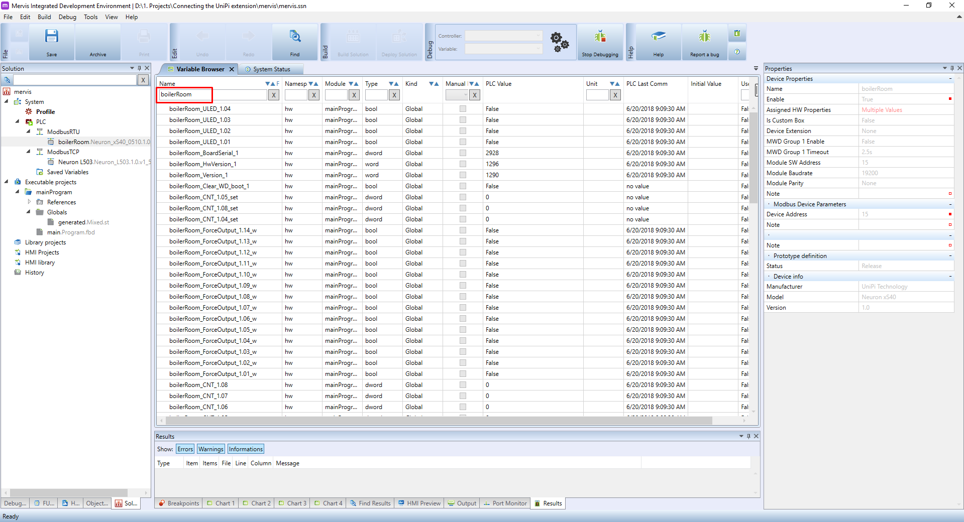
You can try changing the values of boilerRoom_ULED_1.01 and you should see the LED X1 on the extension turn ON and OFF.
Reconfiguration of the Unipi extension
We already learned that you can set a subset of the communication parameters by HW DIP switches. Now we will learn, how to set those in Mervis.
To set the parameters, you need to have a working connection with the extension. We already have this in our current project, so let's continue.
The parameters are configured on the device itself. Select the extension in the Left panel and check the properties on the Left panel.
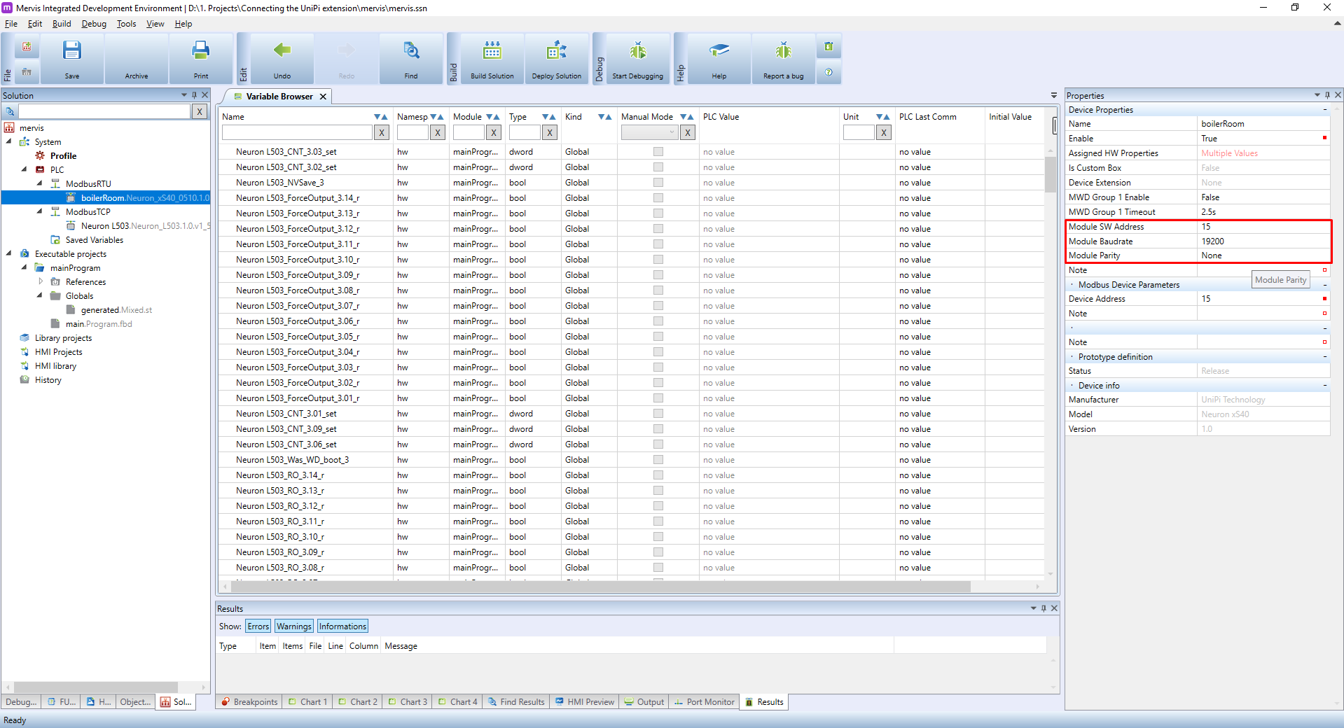
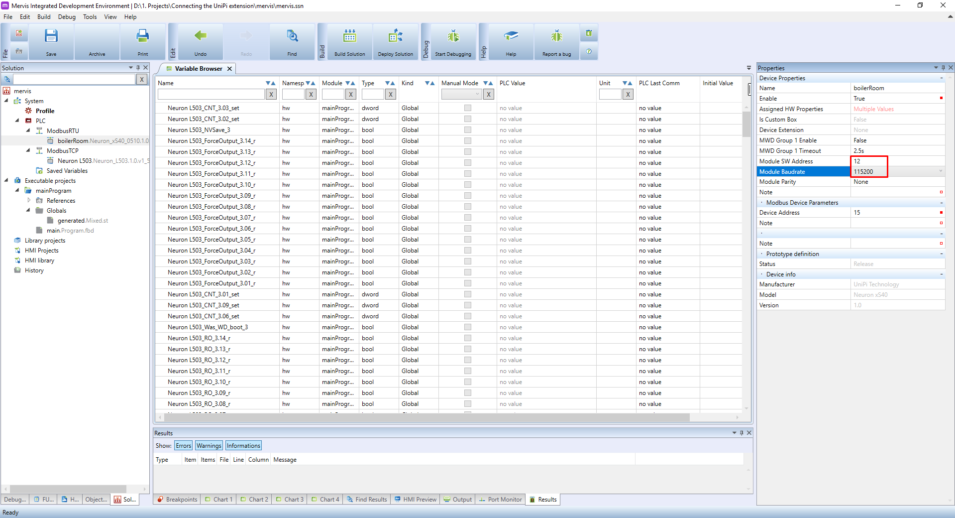
In Mervis, we can set address, baud rate and parity. The data bits will always be 8 and stop bits will be 1. So let's change the parameters to address = 12 and baudrate = 115200.
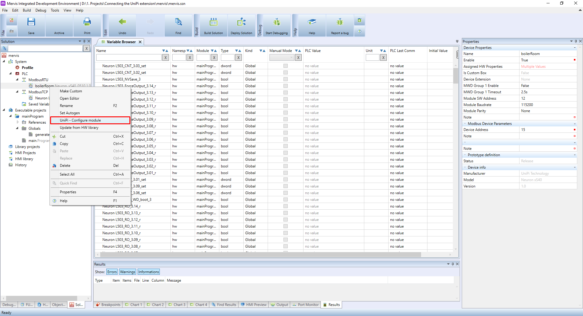
To save these settings, you need to configure the module. Right-click on the extension in the Left panel and in the context menu, click on UniPi - Configure module.
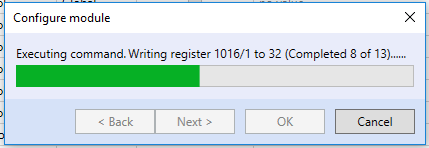
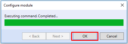
You will probably be asked to switch to Commissioning mode as with the autodetection. After confirmation, you will see a progress bar of the configuration. After the configuration finishes, confirm the dialogue by clicking on OK
We downloaded the configuration into the extension, but to apply the settings, you need to restart the extension as well.
Now that we changed the configuration of extension, we need to do changes in the project as well. Remember, that our ModbusRTU channel is configured to 19200bps. We need to change it to 115200bps to match the speed of the extension. You should know the drill: select the channel in Left panel, change the Baud Rate property in the Properties panel to 115200 and don't forget to Deploy the solution afterwards.
If you run the UniPi - Modules autodetect again, you should find the extension on new address 12. You could import the new device, but then you would have two devices under the ModbusRTU channel. An easier way is to change the communication address in the current device's properties. Select the extension in the Left panel and in the Properties panel check the Modbus Device Parameters.
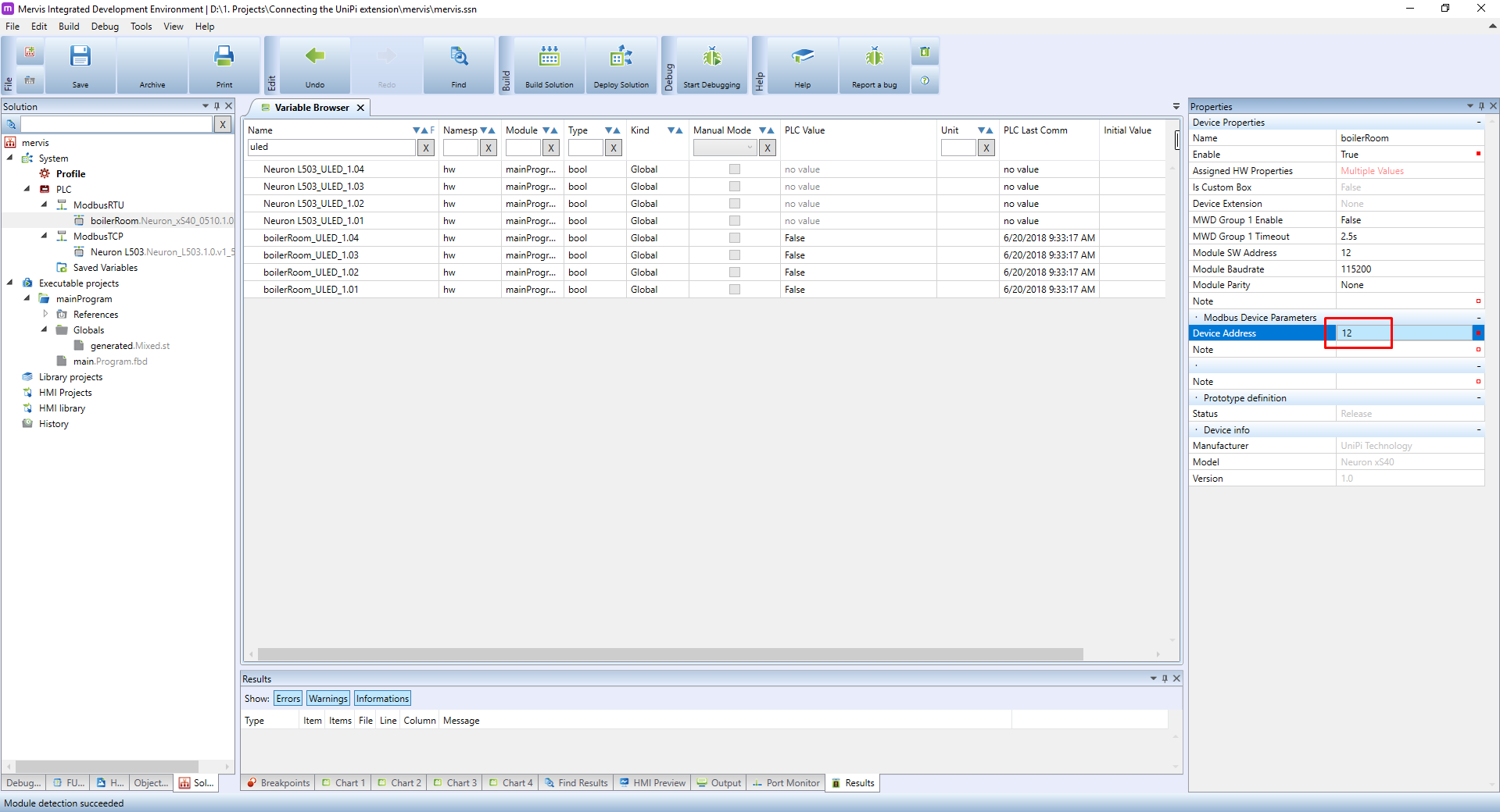
Change the Device Address to match the Module SW Address, Deploy the solution and start the Debugging. In the Variable browser you should see all the properties and their current value.