This is an old revision of the document!
Creating a HMI for local PLC webserver
Create a new project or integrate into an already existing one.
Creating a template
To add a template a PLC must be attached to your project.
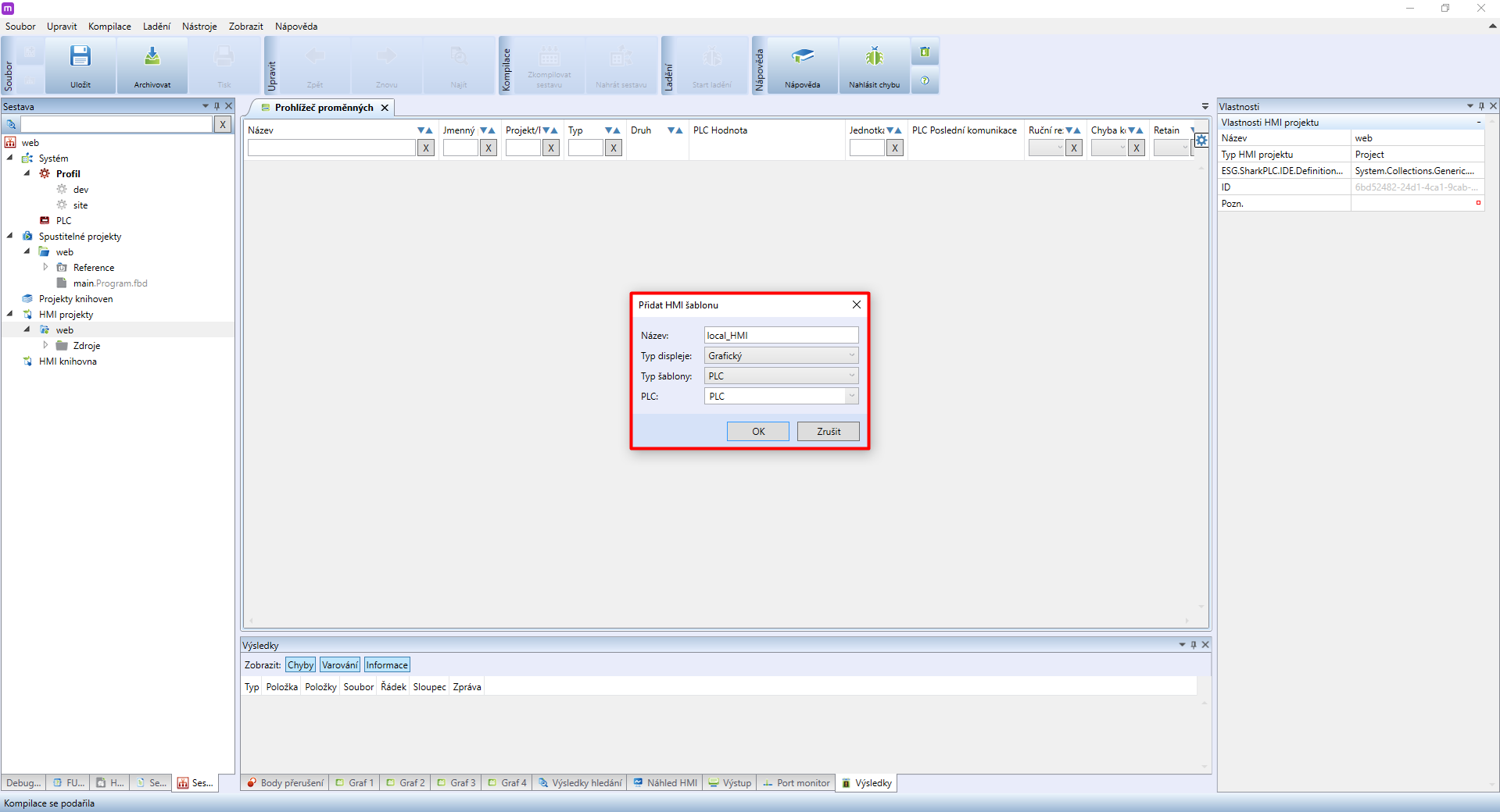
- Name should be considered carefully. We recommend using a prefix separated by an underscore, ie. LOCAL_name
- Display type determines the template type → select Graphic
- Template type - select your PLC
- PLC - select the PLC the template is created for
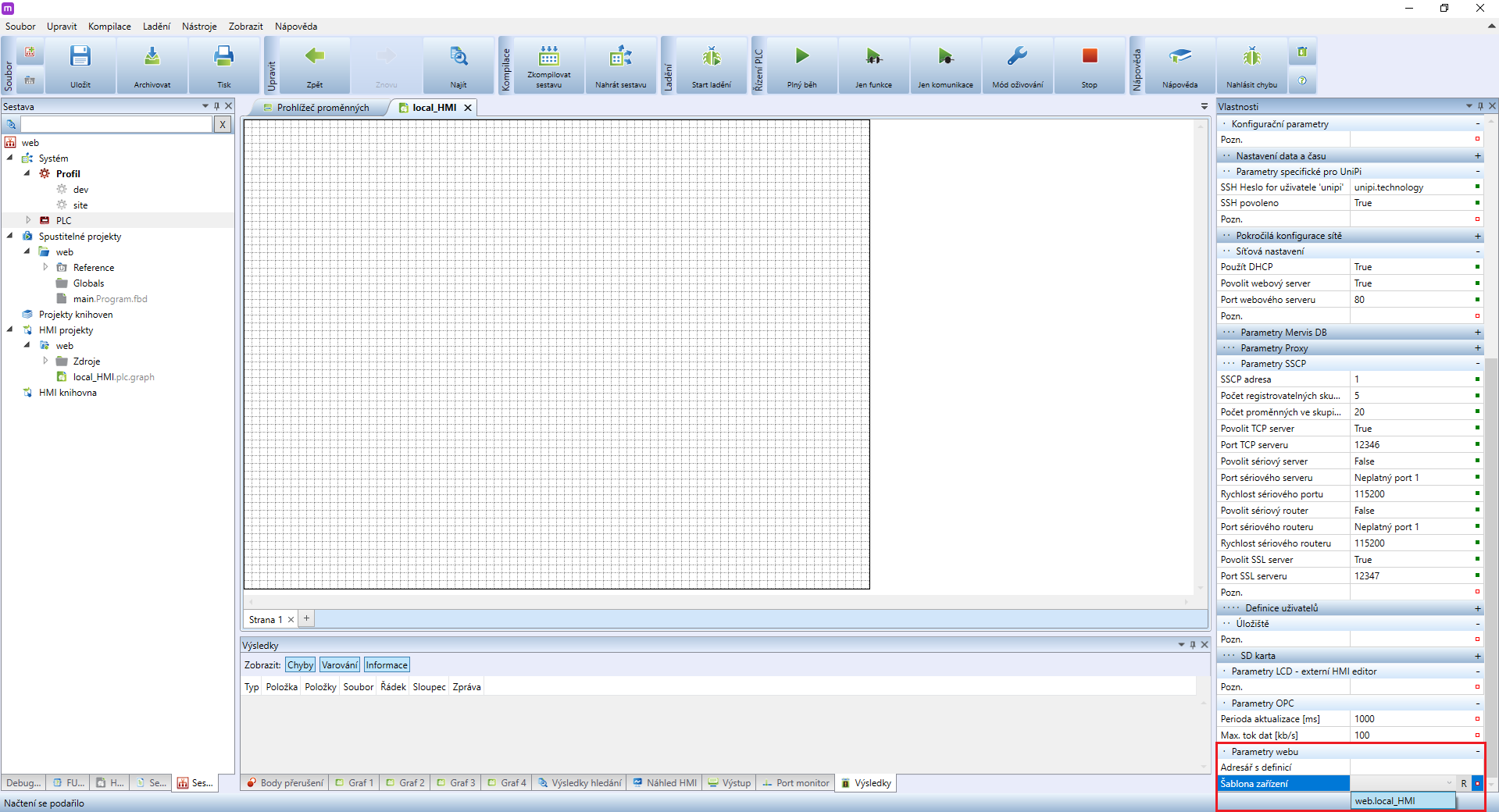
You now need to assign the template to your PLC. Click on the PLC and in its properties in the right column look for Device template. Insert the previously created template here.
Creating a HMI
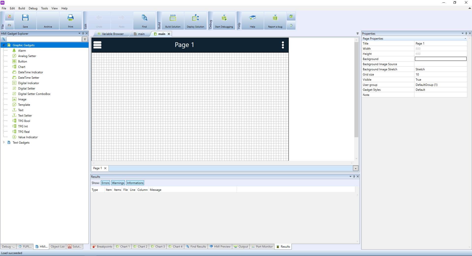
In the left panel, double-click on the created HMI template. On the bottomn of this panel, switch to HMI Objects tab - your screen should look like this afterwards:
In the HMI objects window you can see a wide collection of graphic gadgets that can be added to the template. In this tutorial, we will start with the Value Indicator element designed for displaying numeric values. This makes it ideal for displaying the current temperature in an office, for example. Click on the element in the left panel and drag it onto the main panel.

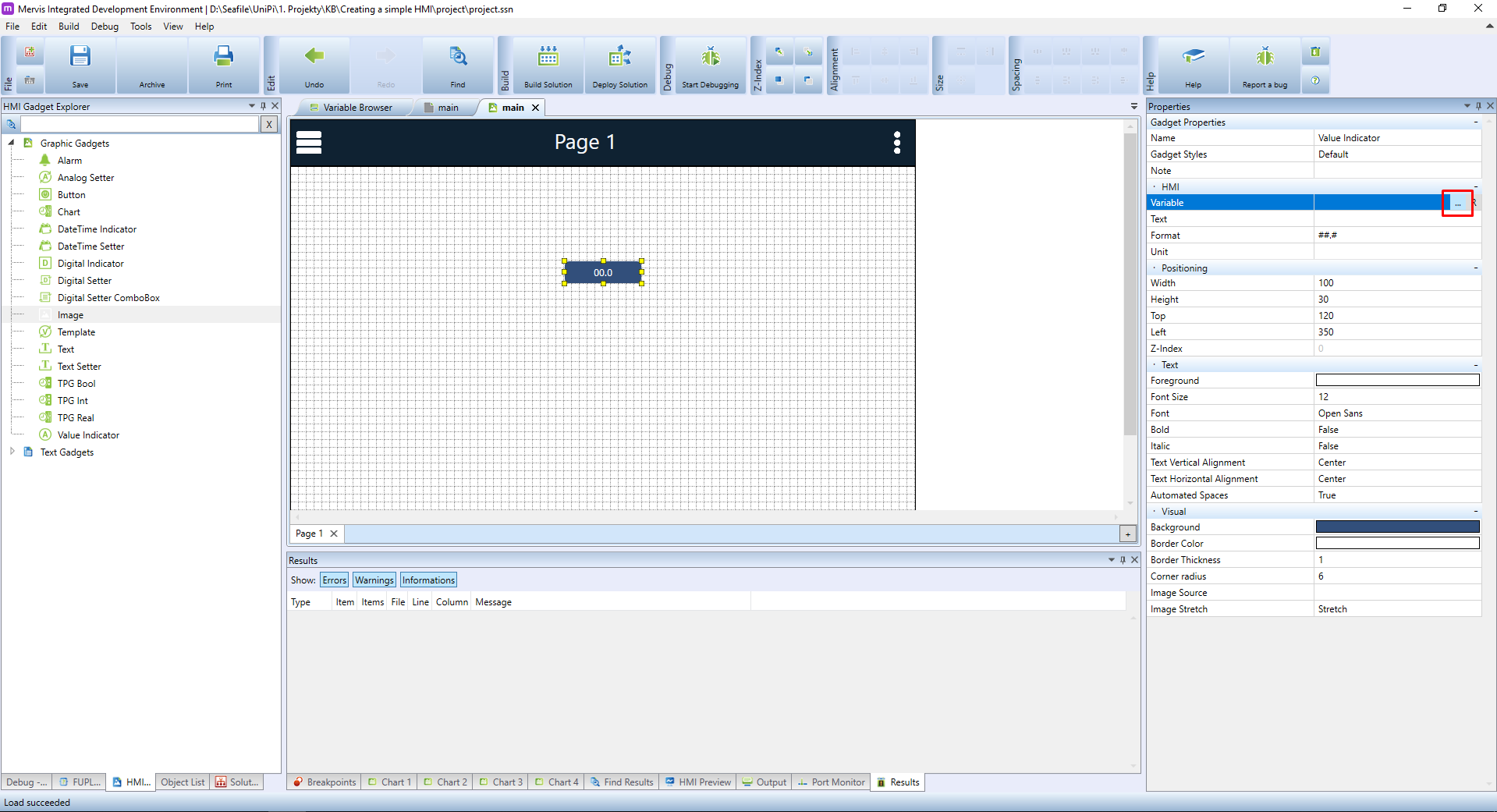
The element will appear on the main panel and will stay highlighted. In the Properties menu, you can now see all available configurations for it. Right now, the most important attribute is Variable placed in the HMI section. Using this setting we will tell the element which variable will be used as a data source. Click on Variable and then click on the button.  .
.

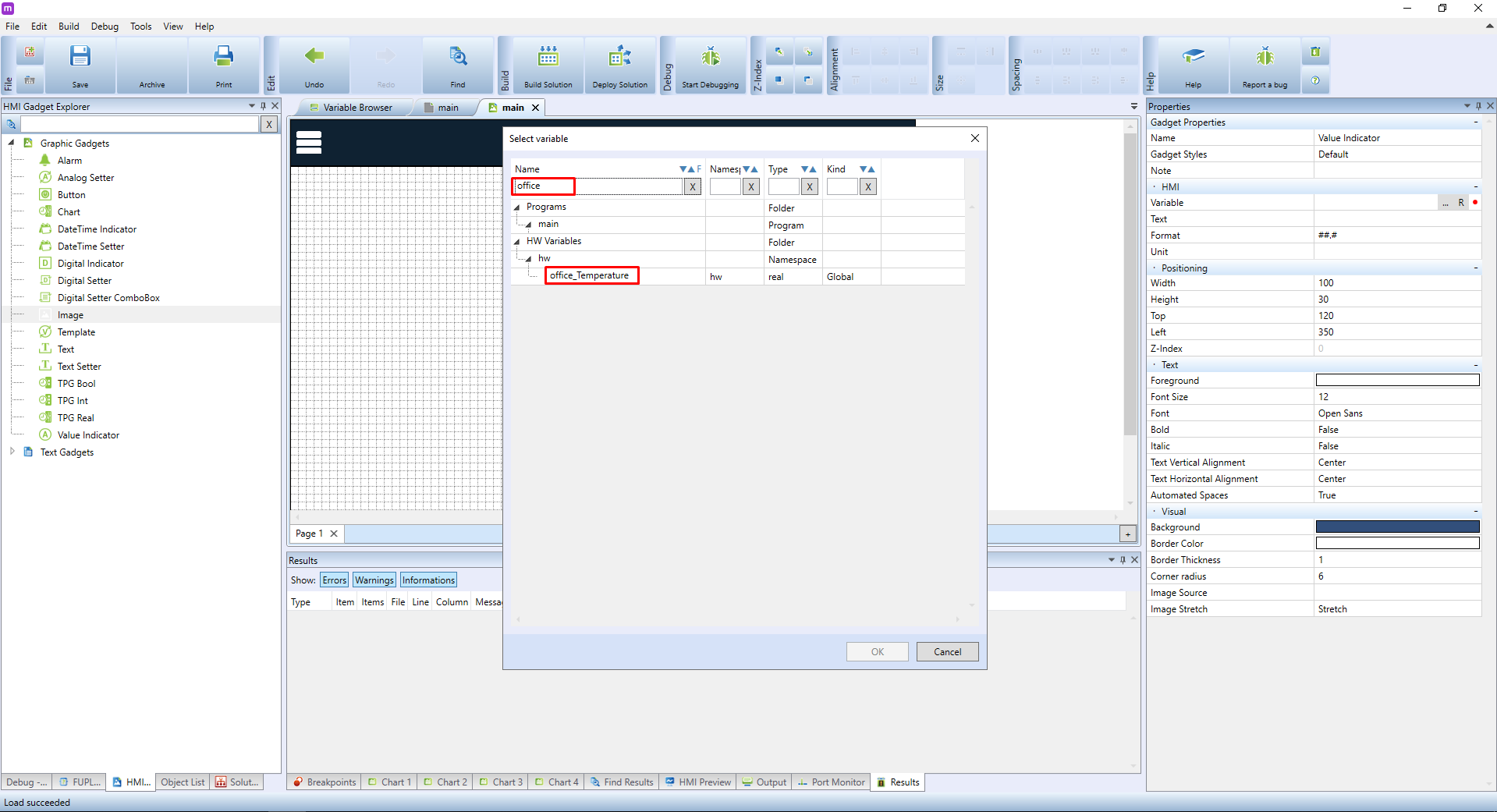
A well-known Select variable dialogue will appear, in which you can search for the needed variable. In this tutorial, we are looking for an already existing office_temperature variable. Look it up, select it from the list and confirm by clicking on OK.
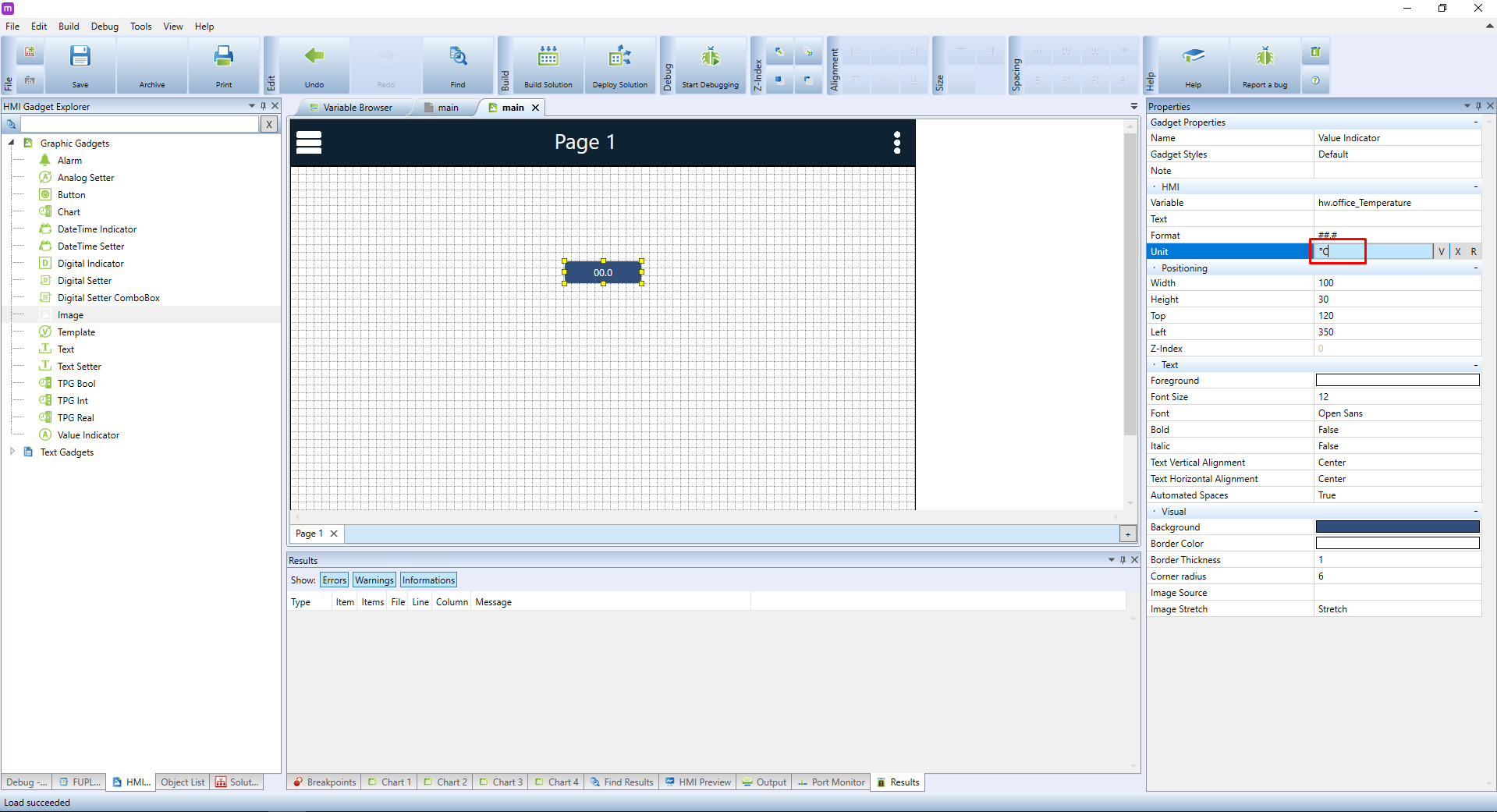
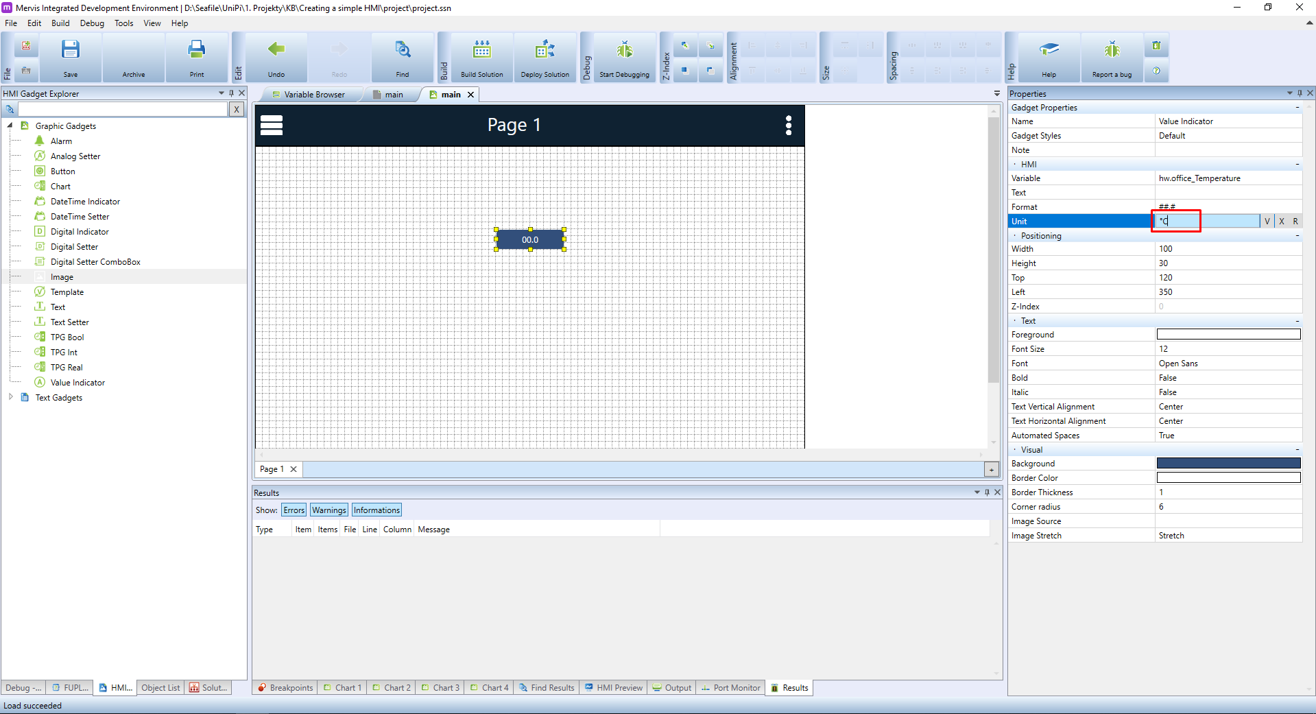
Go back to Properties. Change the Unit setting determining the displayed value's unit. In the HMI, this unit will be automatically added behind the displayed values. As we are talking about a temperature value, set the Unit attribute to °C.
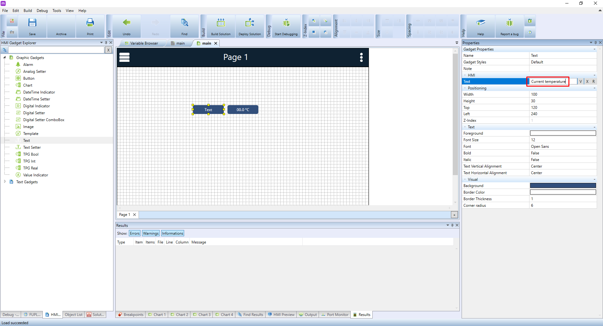
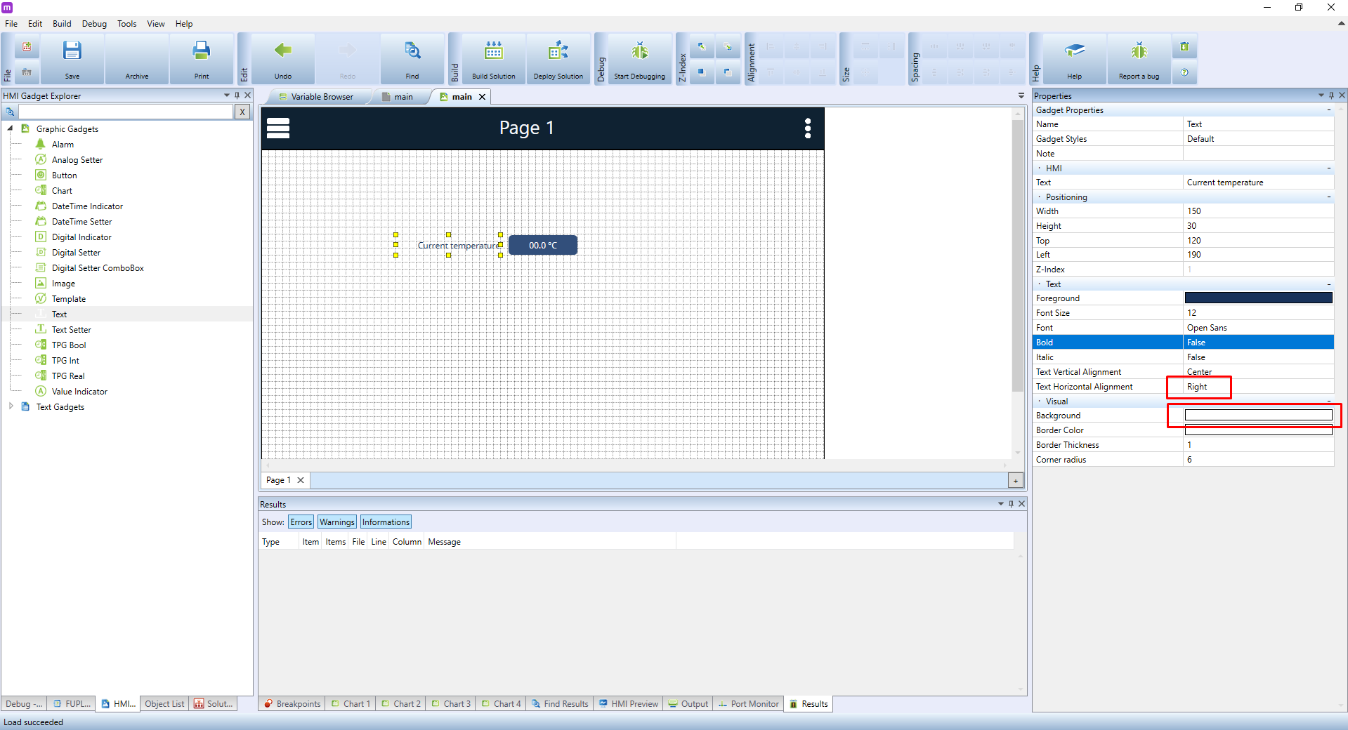
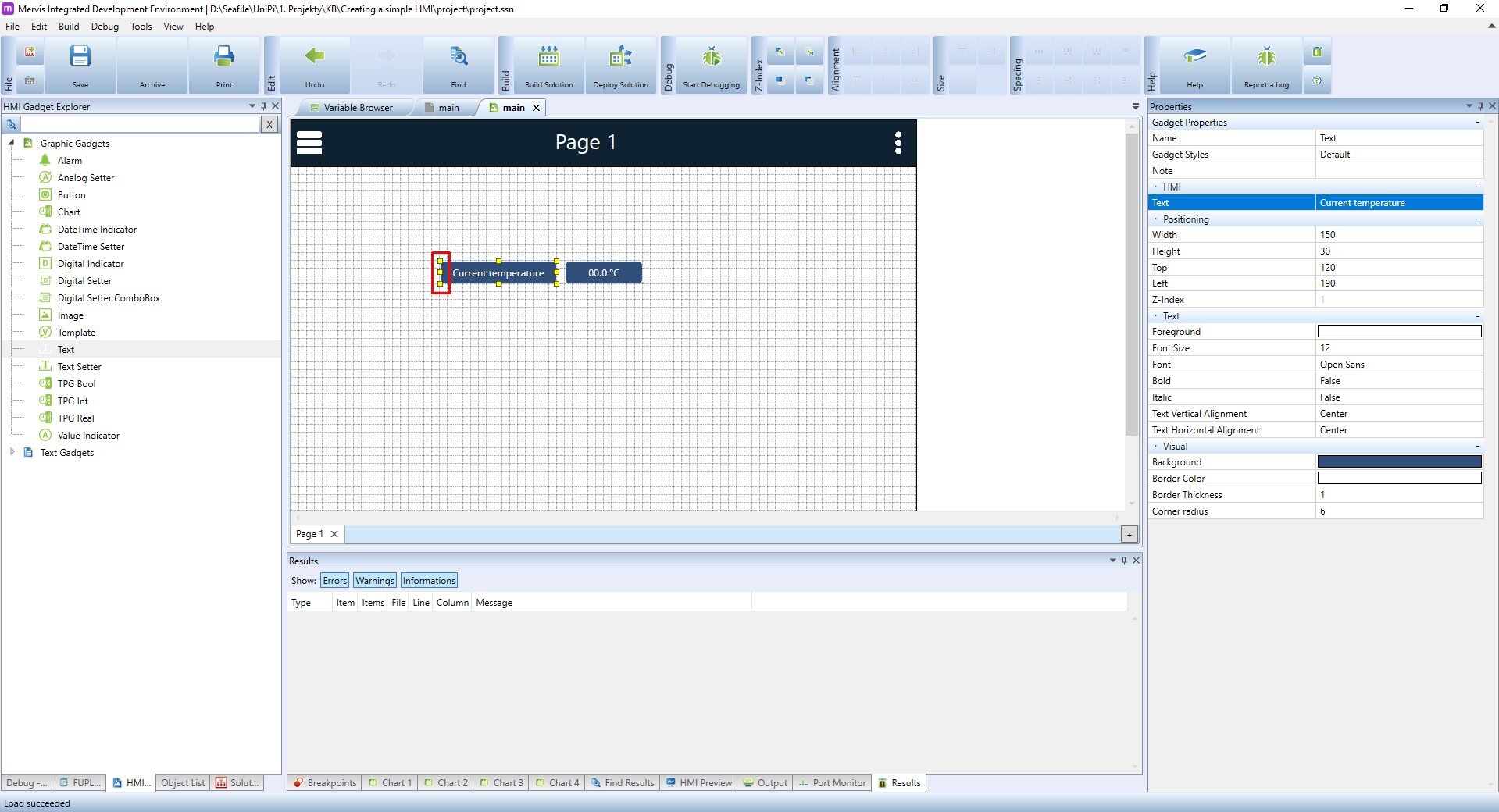
It may be also handy to give the value a suitable name. In the HMI objects menu choose the Text element and place it into the template. In the Properties panel, change the Text attribute to Current temperature.
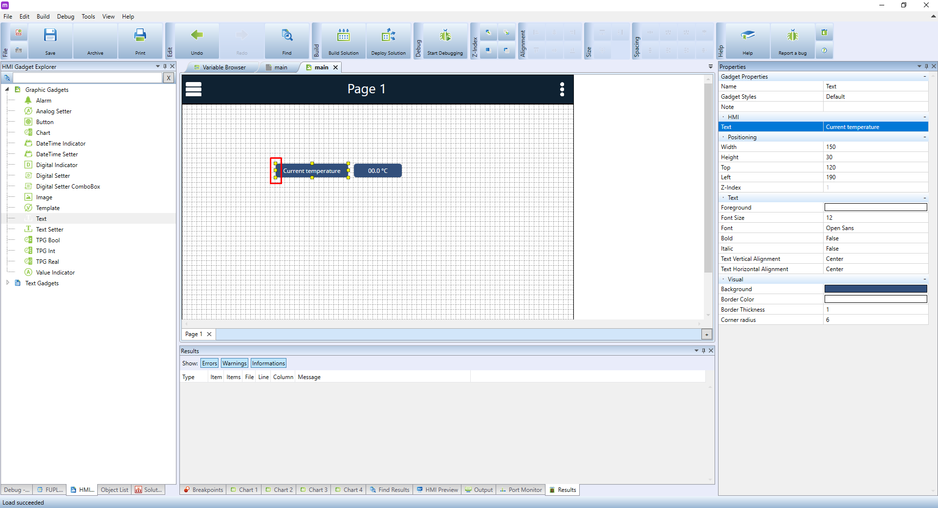
As the new name is much longer than the default one, you can enlarge the text field by dragging one of the yellow squares around the element to make the whole text visible.
Right now, the element is not legible enough, and its current design makes it look more like a button than a nametag. Let's improve it by changing the text's colour to blue using the Foreground attribute in the Text property section.

Now change the Background colour to white, and Text Horizontal Alignment to Right.
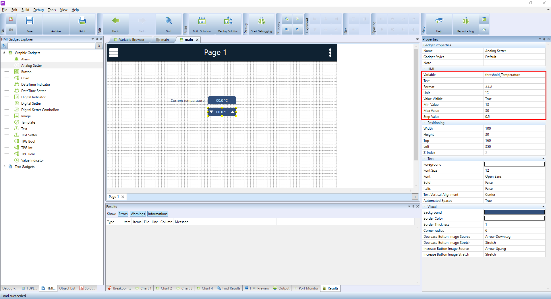
The next step is to add an element that would allow us to display and configure the values of an analogue variable. Theoretically, we could again use the Value Indicator. However, this element can only display values, not change them. A more suitable choice is the Analog Setter. Select it and place it onto the canvas. In the HMI properties, configure it as follows:
- Variable: choose a suitable variable representing temperature. In our case, we will select threshold_temperature variable
- Unit should be set to °C as the variable is expressed in degrees Celsius.
- Min Value will be 18, which will prevent users to set a temperature lower than 18 °C
- Max Value is 30 to prevent users to set a temperature higher than 30 °C
- Step Value, or the increment by which the temperature can be adjusted. Set it to 0.5
We will also create a text label for the element in the same way as with Current temperature. You can simply copy and paste the text fields and edit the text afterwards.
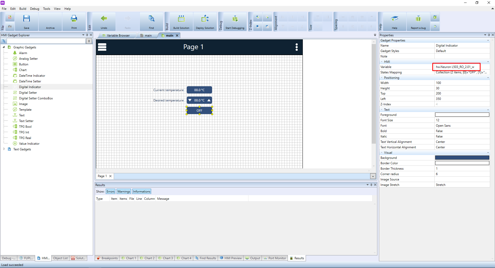
The last element we will need is an indication of heating status, eg. if the heating is ON or OFF. Again, we could simply use the Value Indicator, but we won't since this element can display only binary values (0 or 1). A better choice is the Digital Indicator. Select it and place it onto the canvas. Here, you need only to select the correct variable, ie. DI_1.02.
We recommend giving inputs/outputs descriptive names such as light_kitchen, door_bell etc. There are two main reasons:
- Such names will make the project much clearer and easier to read
- If you decide to plug a sensor to a different input, all you need to do is to rename the input variable with the rest of the program still using the same name
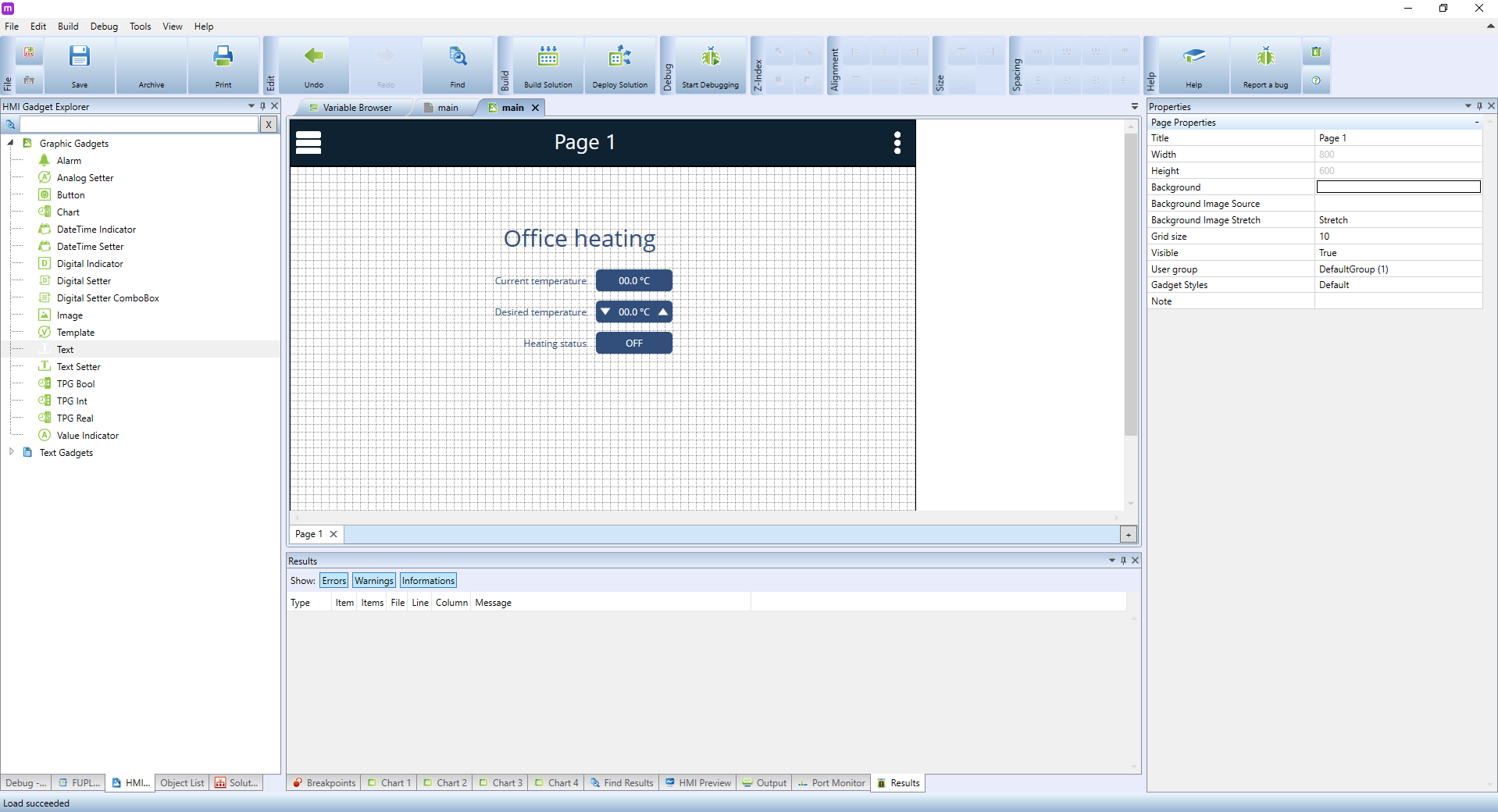
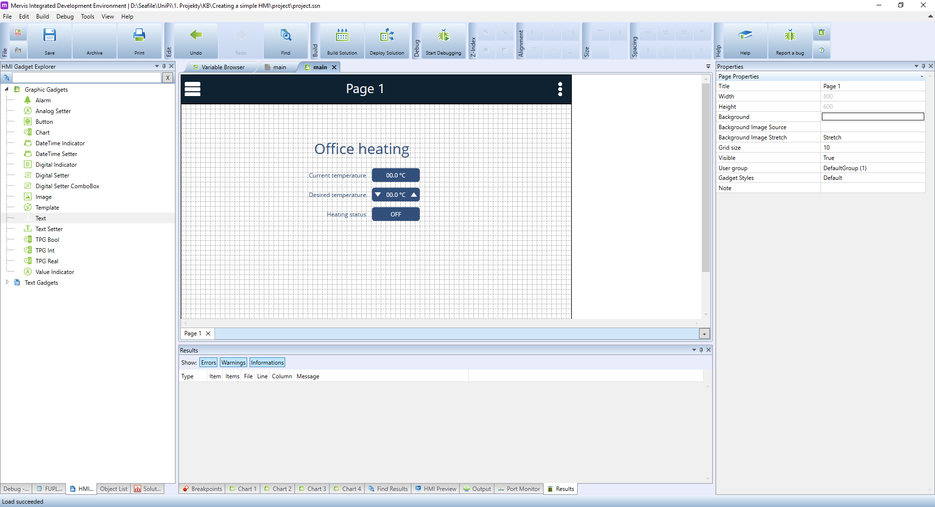
At this point, only a couple of finishing touches is needed. Give the heating status indicator a name and then create another, a larger text field for the name of the entire HMI project. The result can look like this:
Securing a HMI
Securing an HMI is an important step to set users and user groups and grant them access to the HMI. If the default login remains unchanged, any user connected to the network can access the HMI using default passwords and is able to change PLC values. You should never allow users to access the HMI through a public IP, as the webserver on the PLC should be used only on a local network. To access the HMI from the internet, use the Mervis SCADA.
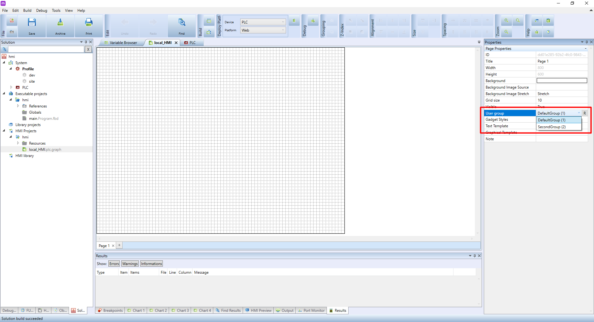
In the properties of each HMI page you can set a group of users able to access the said page. Each user can be assigned to single or multiple groups. Each group can be also set for both read/write or as a read-only.
By double-clicking in the left panel you can open:
- PLC (local webserver)
- Terminal (external webserver).
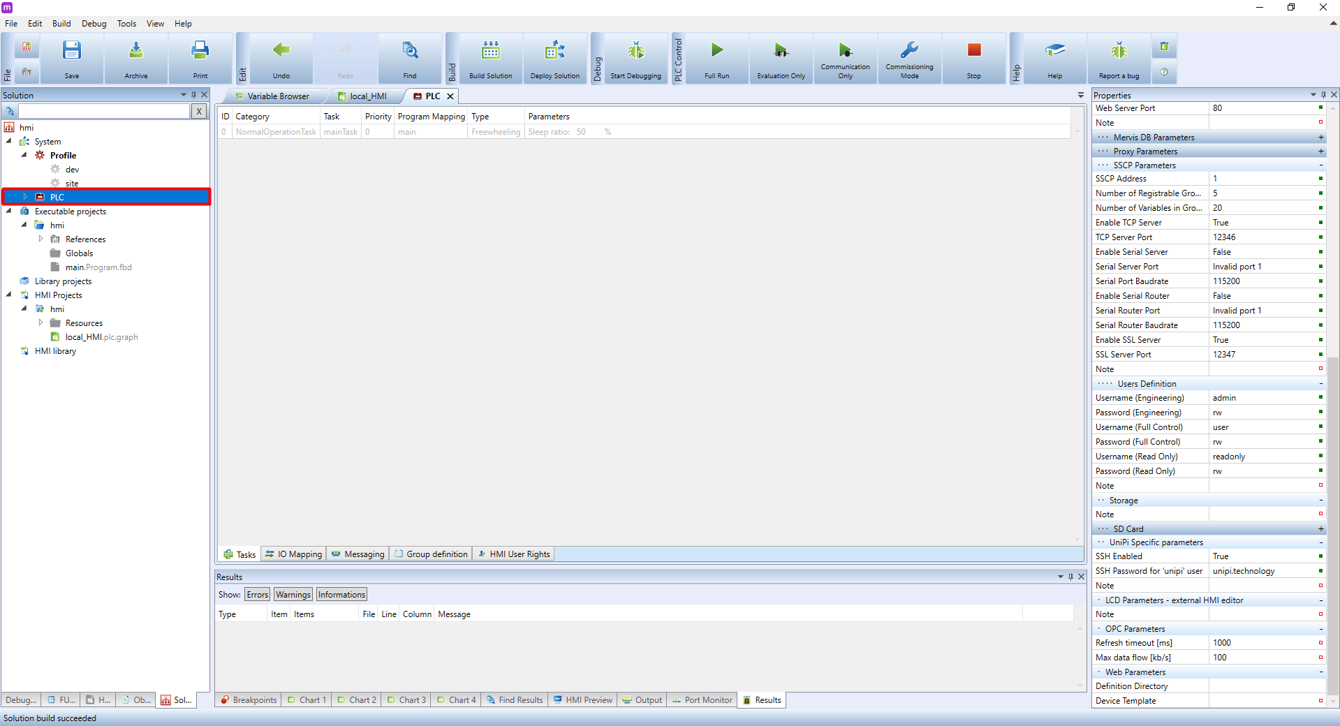
In the bottom panel of the PLC windows, look for HMI User Rights.
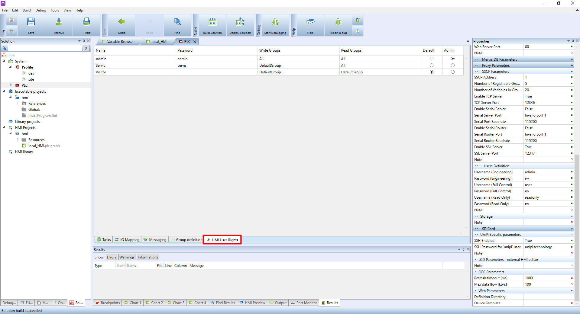
A list of users will appear. Change the default passwords immediately. You can also set a separate read-only or write user groups. The last two columns are for setting up which user will have admin rights and which will be the default one. If the default user has no password, the HMI will display with no password needed. If you use this setting, we recommend setting this user as read-only.

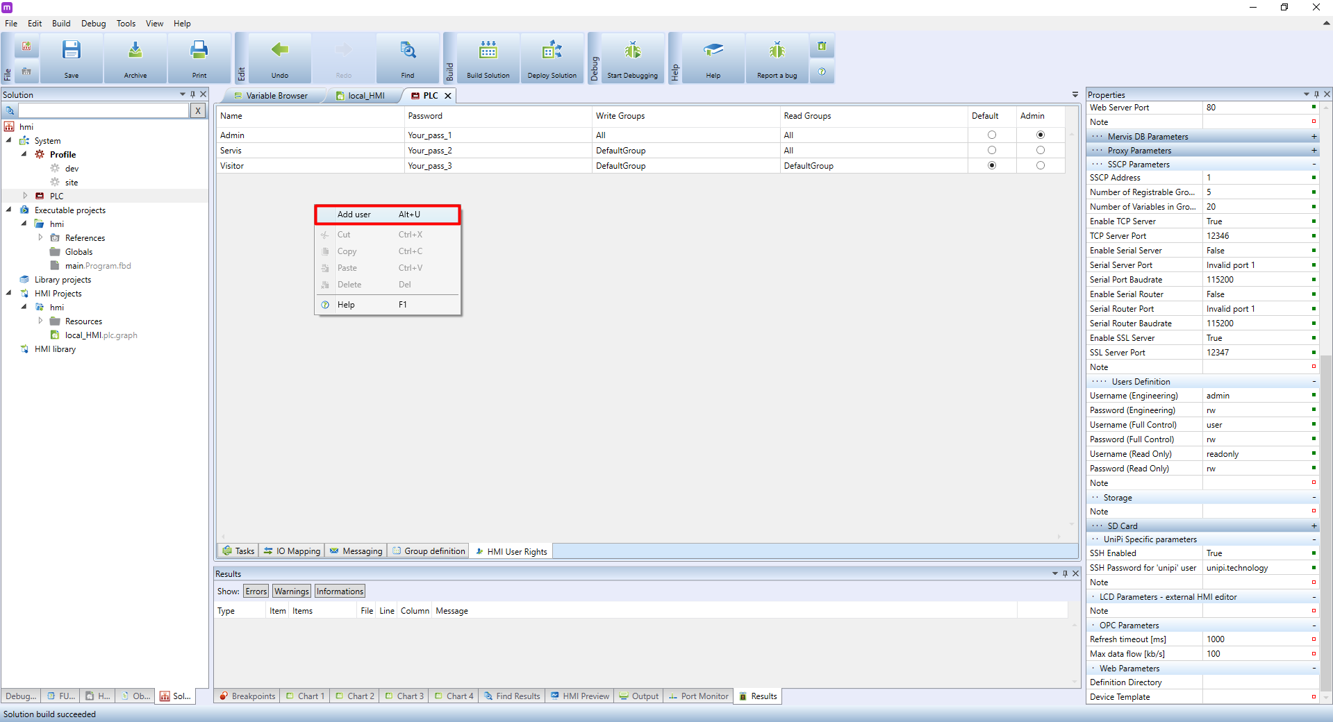
If you right-click into the blank space under the user tab, a menu will appear. Here, you can add more users. The rest of the options are for editing existing users and are available via a right-click on any of the users.
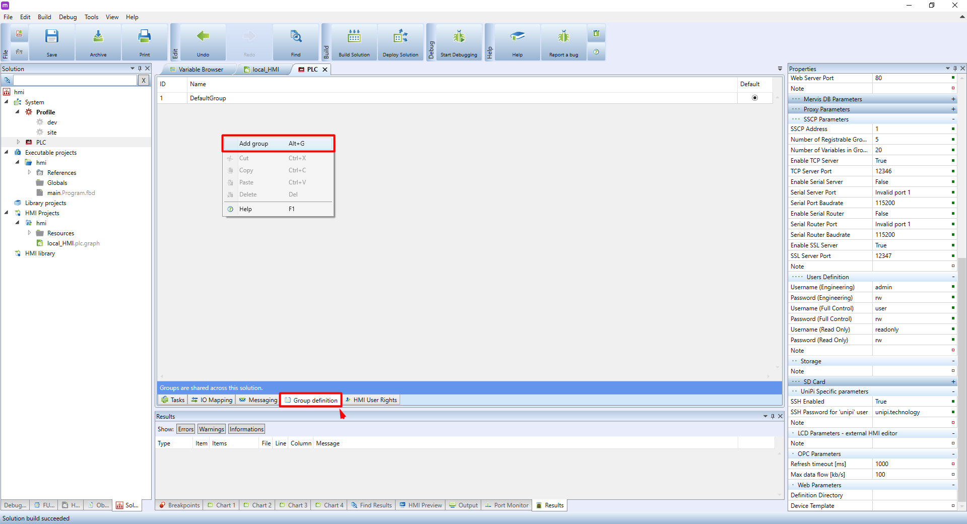
By clicking Group Definition tab on the bottom of the PLC window, group settings will open. In this panel you can add or manage user groups the same way as users, including a column for selecting a default group, which will be assigned automatically to every additional user.
All changes need to be confirmed to save them. Confirm by clicking OK in the red bar.
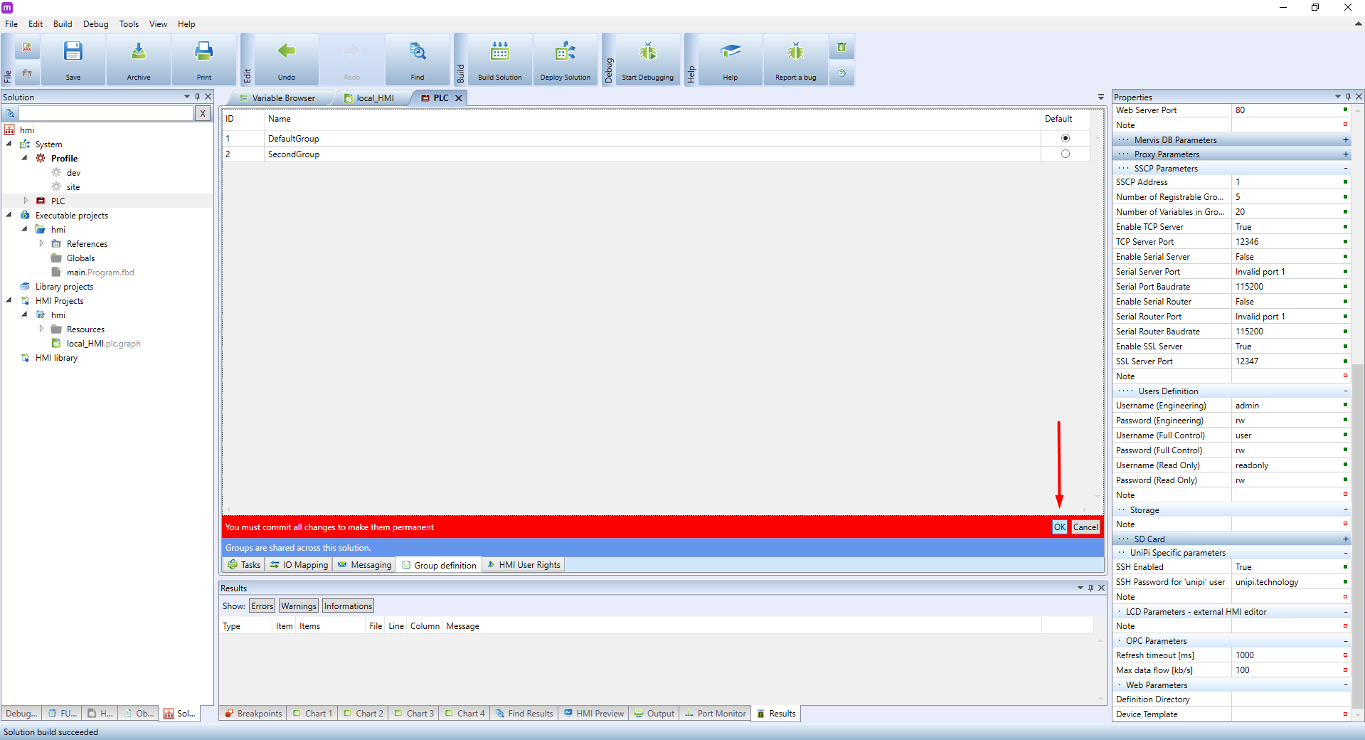
Below you can see an example of user configuration.

In the properties of each HMI page, you can set a user group able to access the page.
Deploying a HMI into a PLC
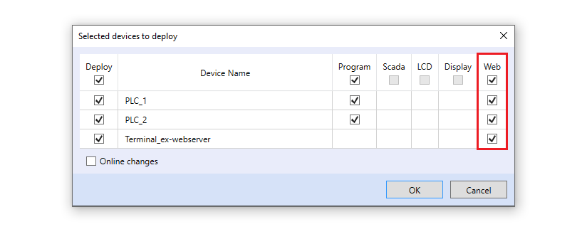
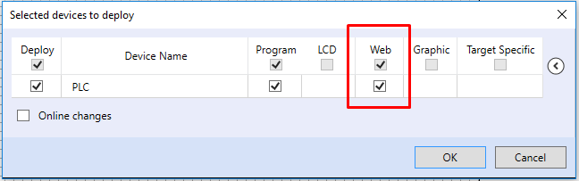
To deploy a solution, click on Deploy Solution. A deploy dialogue window will appear. Make sure to check the Web box next to the PLC/terminal. With an external web server, check that only the specific web server is being uploaded (eg. not the local one).
Downloads
The entire Mervis IDE project used in this tutorial is available for download on this link
Creating a HMI for local PLC web server
In this tutorial, we will demonstrate, how to create an HMI (human-machine interface). The HMI is a graphical interface displayed on the touchpanels or in a web browser, which allows to show the status of the automation process and to control it. In this tutorial, we will focus on the built-in HMI capabilities of Mervis, which runs on the UniPi controller and is accessible via a web browser.
The goal is to continue with the previous “temperature regulator” project. We will display the current temperature in the room, set the threshold temperature a display if the heating is ON or OFF.
Prerequisites
- UniPi controller running Mervis OS
- Temperature requlator project from previous tutorial
In this tutorial, we will use Unipi Neuron L503.
Creating HMI
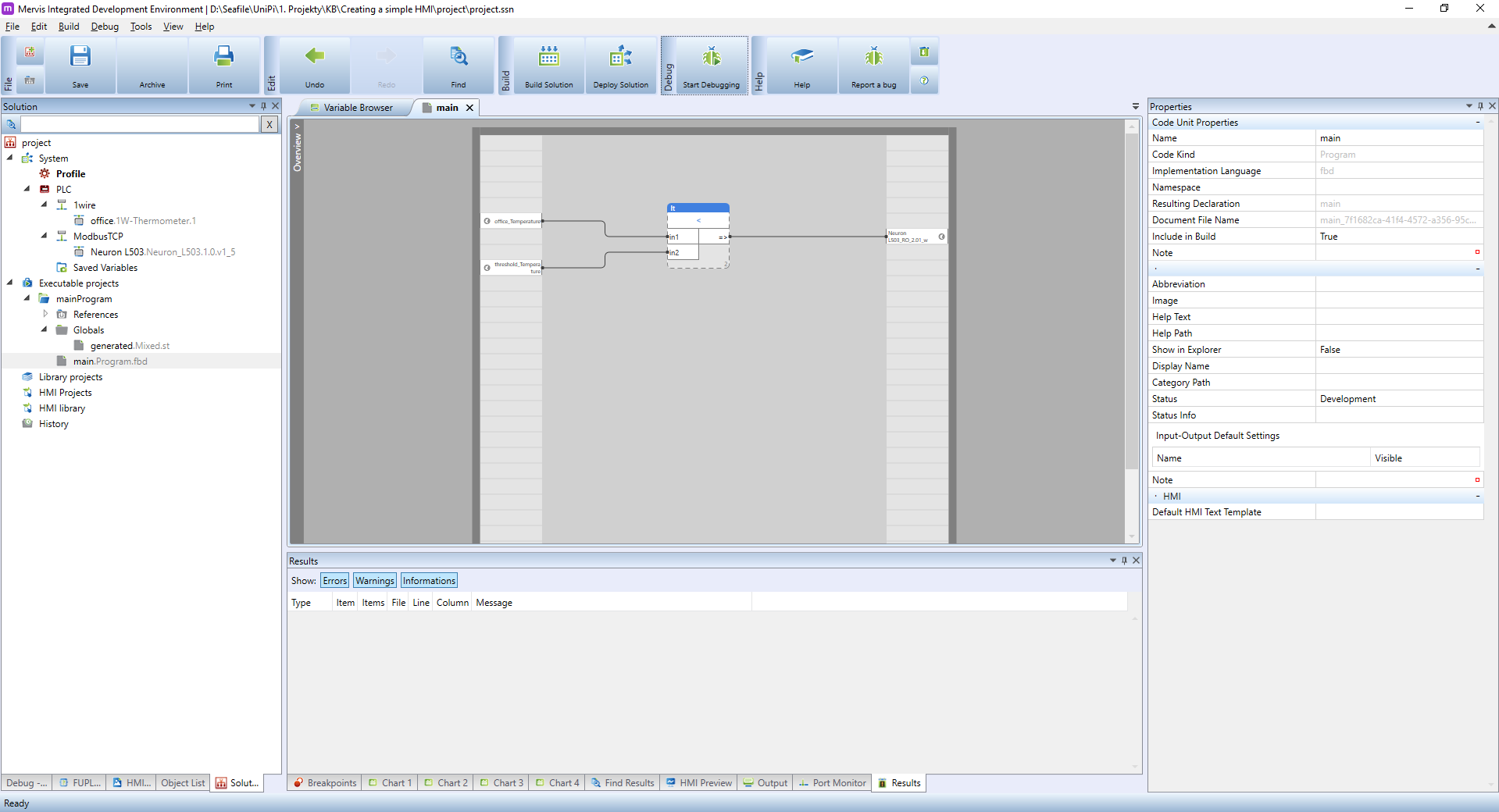
If you use previous tutorial, your workspace should look like this:
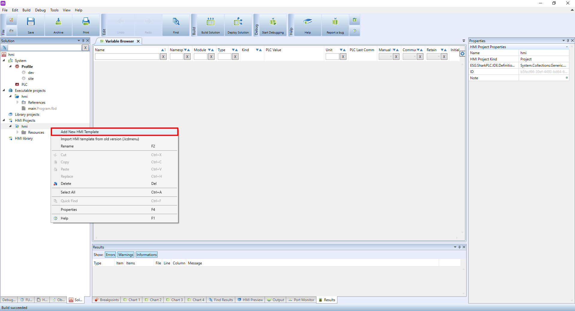
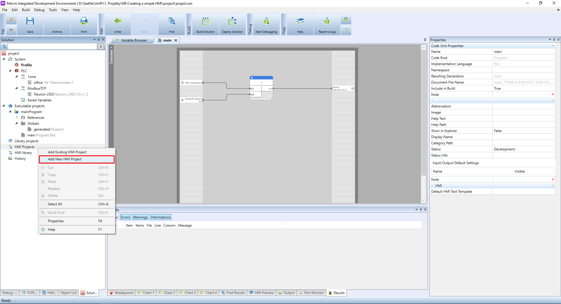
In the Left panel, you can see HMI Projects, under which we will create a new project similarly as with Executable projects. Right-click on the HMI Projects and from the context menu select the Add New HMI Project.
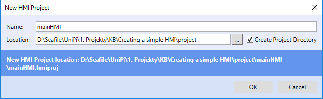
A New HMI Project dialogue will appear. Pick a name and location of the HMI project files. It's not uncommon to have them in the same directory as the Mervis project. If so, tick the Create Project Directory as well. And confirm by clicking on OK.
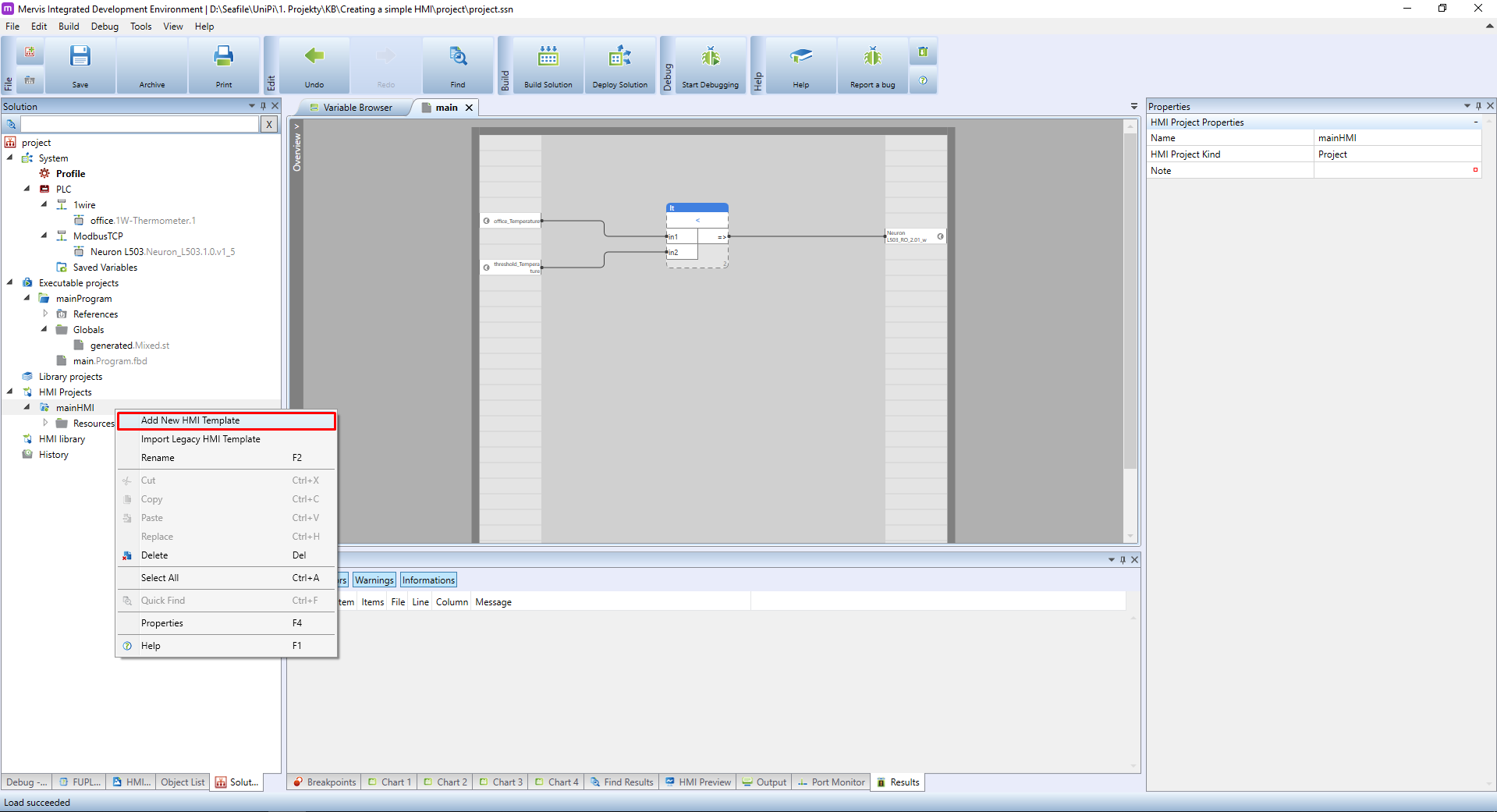
A new project appeared under the HMI Projects in the Left panel. Right, click on the project and from the context menu select the Add New HMI template option.
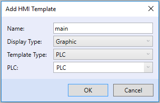
An *Add HMI Template* dialogue will appear. Pick a name for this template and fill the rest of the options as follows. The PLC Template type will assure the presence of all the PLC's variables in the HMI template.
Once you confirm the dialogue, the new template is created and opened. In the Left panel switch to the HMI Gadget Explorer. Now you should see similar workspace:
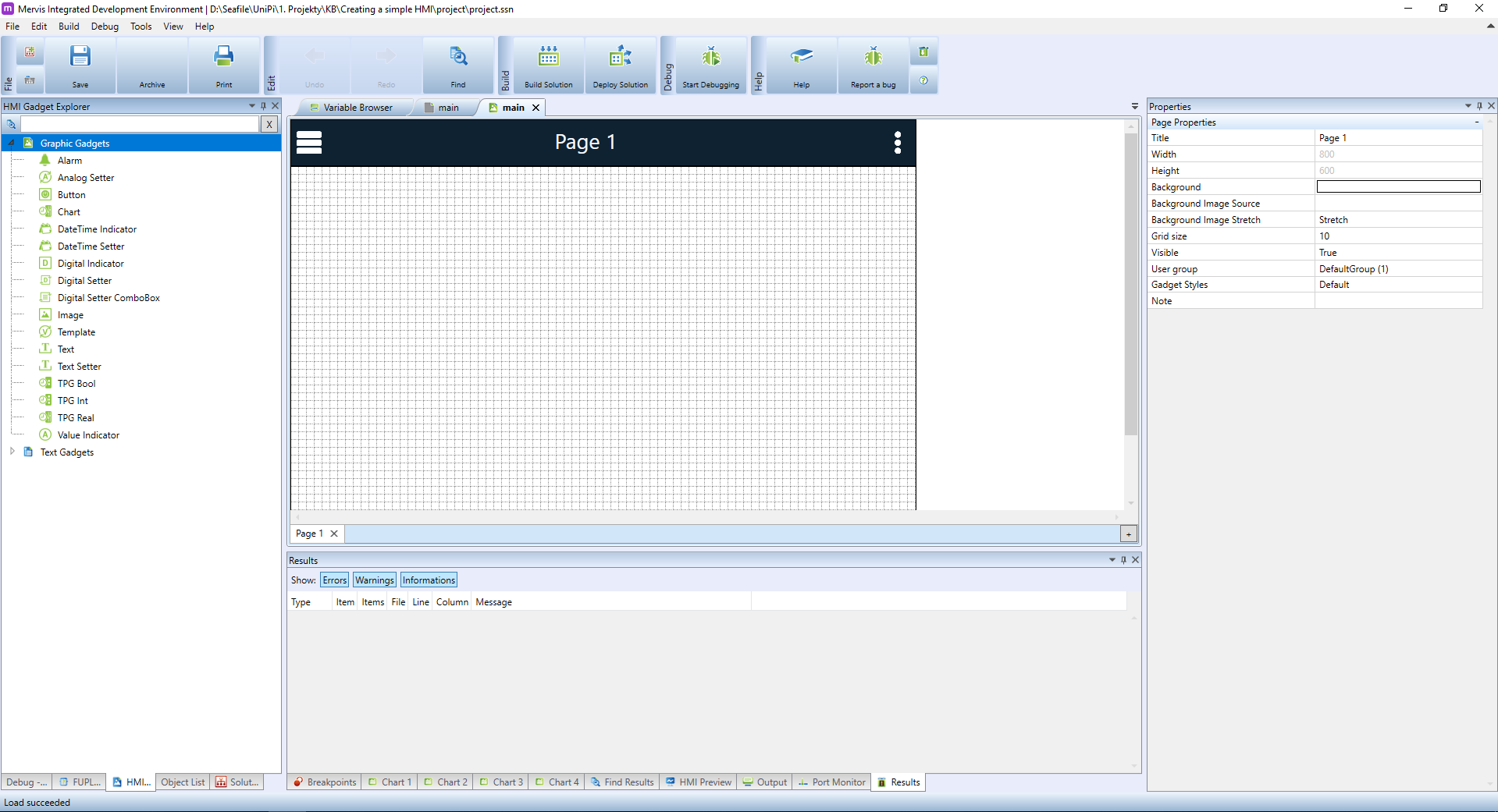
In the HMI Gadget Explorer you can see all kinds of graphical elements, which we can place onto the template. We will start with element Value Indicator, which can display numeric value. Perfect for displaying the current temperature in the office. Click on the element in the Left panel, hold the button, move it over the template in the Main window and release the button.
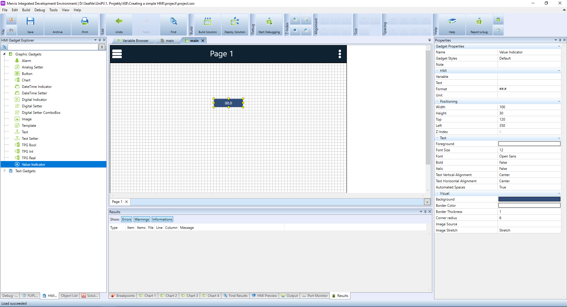
A new element is created and automatically selected. In the Properties panel, you can see all the properties you can set for this element. The most important is the Variable property under the HMI section. Via this property, we will tell the element what is the source of data to display. Click on the Variable property and then click on the … button.
A known Select variable dialogue will appear, where we can search for the variable we created in the program: the office_Temperature. Search for it, select it in the list and confirm by clicking on OK

Back in the Properties panel, we can change the Unit of the displayed value. This will be appended to the value inside the indicator. Since this indicator is for displaying the temperature in Celsius, set the Unit to °C.
Now we would like to label this value. From the HMI Gadget Explorer pick the Text element and place it on the template. In its properties panel change the Text to Current temperature.

Since the new text is larger than the size of the element, you can resize it by grabbing the yellow boxes around the selected element.
The text element is also not very easy to read and the look rather indicates it is a button, tied to some function. Let's change the text to dark blue, by changing the Foreground property in the Text section of properties.
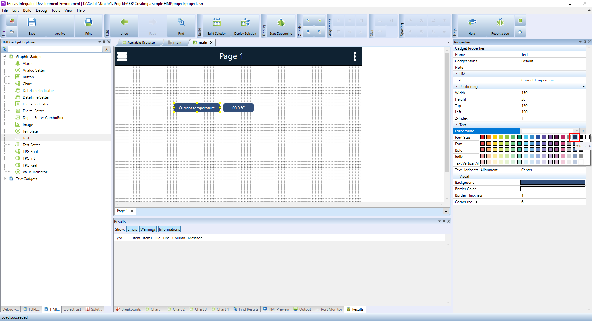
And change the Background to white and the Text Horizontal Alignment to Right as well.

Next element we need is for displaying and setting the value of threshold_Temperature. We could use the Value indicator, but this element allows only displaying the value, not changing. More suitable element is the Analog Setter. Pick and place it onto the canvas. In the HMI section of its properties set the following:
- Variable to the threshold_Temperature we created in the program
- Unit to °C since the variable is the temperature in Celsius
- Min Value to 18 because we don't want to allow the user to set the temperature lower than 18°C
- Max Value to 30 because we don't want to allow the user to set the temperature higher than 30°C
- Step Value to 0.5

Also, create a text label for this element as we did with the Current temperature. You can copy and paste the previous text label and just change the text.
The last element we need to place is an indicator of whether the heating is ON or OFF. We still could use the Value indicator, but it would display only values 0 or 1. It is better to use the Digital indicator element. Pick and place it onto the canvas. And the only thing we need to do is to point it to the correct variable. We didn't name it nicely, so you need to look for the RO_2.01.

It is always a good idea to rename the actual inputs/outputs to something meaningful, like kitchen_light, door_bell, etc. The reasons for this are (at least) two:
- It makes the program more understandable
- If you decide to physically rewire the sensor to another input, you just rename the input variable and the rest of the program will use the same name
Let's do some final touches. Create a label for the heating status, and create another, a larger label indicating what is this HMI page about. The result could look like this:
Now it's time to upload the HMI to PLC. First, we need to tell the PLC, what type of template it should display. You can have many HMI Projects attached with many templates and PLC cannot pick this automatically. It's the same with programs being executed via Tasks.
Switch to the Solution tab in the Left panel, select your PLC and in the Properties panel scroll down until you see the Device Template property in the Web Parameters section. Select from the dropdown menu the correct template. If you followed the tutorial precisely, there should be only one.

Now Deploy the solution and make sure, that you have Web options selected.
After successful deployment, open your favourite web browser and enter the IP address of your PLC into the address bar. You should be presented with your newly created HMI with up-to-date information.
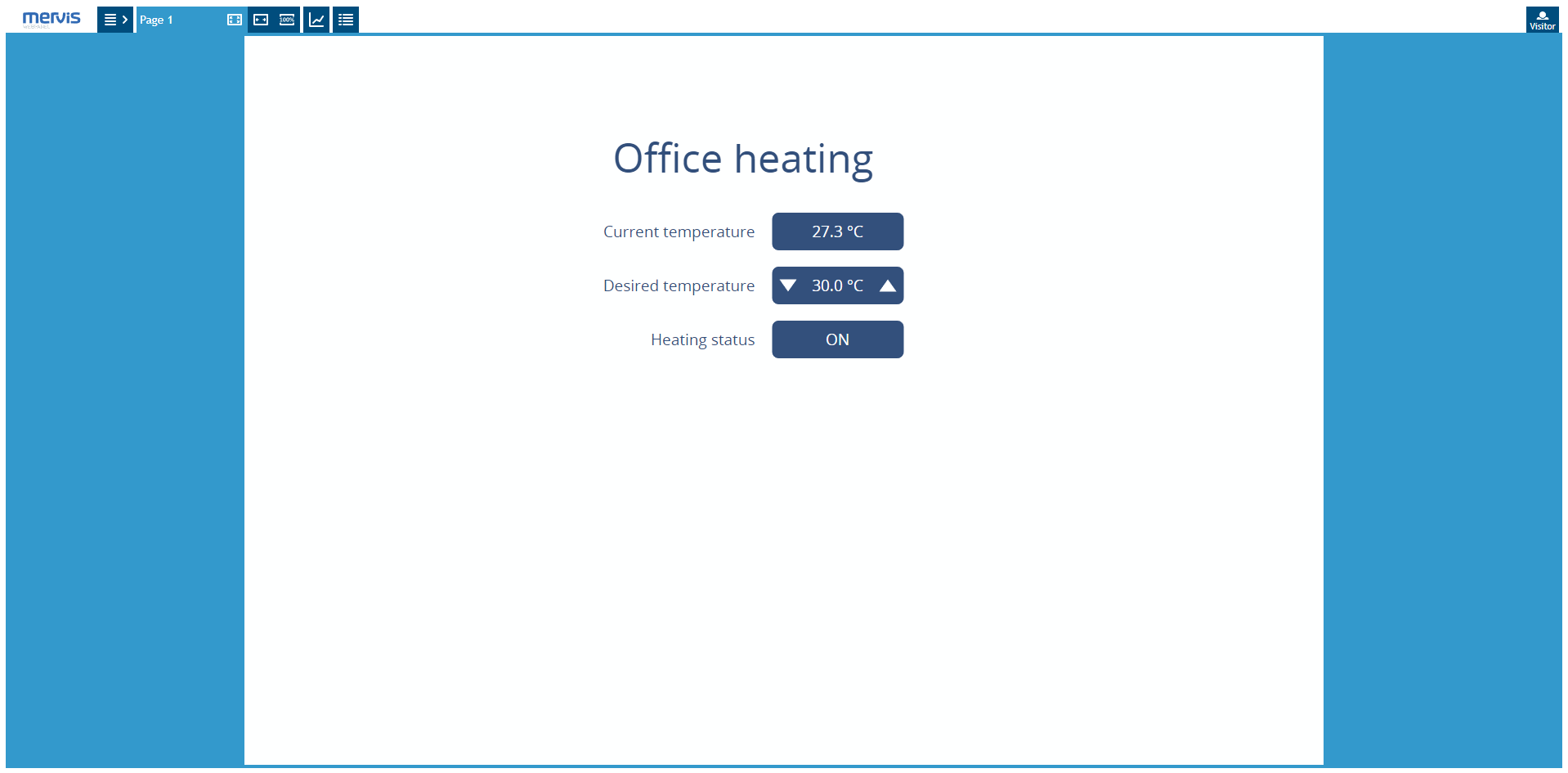
As you can see, the current temperature is 27.3°C, the desired temperature is 30°C, which results in the heating being ON. Change the desired temperature to lower value ten your current temperature and the heating will turn OFF.

Downloads
You can download the Mervis project files here: creating-a-simple-hmi-project.zip