Setting a Modbus server (slave)
So far in other tutorials, we used a Unipi controller as a Modbus master device. That is the download / upload of data to Modbus slaves (Unipi extensions, energy meters,…) were initiated by the Unipi controller. In this tutorial, we will demonstrate how to set Unipi as Modbus server, or in other terminology Modbus slave.
Patron
Neuron
Gate
Unipi 1.1
Axon
Physical layer
As a first thing, we need to decide, what type of physical layer we will use. On Unipi running a Mervis, we can pick either from RS485 (ModbusRTU) or ethernet (ModbusTCP). The decision will be based on the rest of your existing infrastructure and the capabilities of devices, which will communicate with your Unipi.
The RS485 physical layer is typically limited by its speed (115200 bps) and nature of the half-duplex communication, which limits the speed even further. On the other hand, the RS485 is easy to implement and still very popular in industrial automation.
To achieve communication between master and slave, some sort of addressing has to be used. In ModbusRTU, each slave device has to have unique ID or address, which is a number 0-255.
On ModbusRTU network only one device can act as a master. Mervis will not allow you to create master and slave on the same RS485 port. But it cannot warn you, if you are setting master on a network, where another master is already present.
The Ethernet physical layer allows connecting much more devices then RS485 and practically you are not limited by the speed or throughput of the network. With ModbusTCP, you are also not limited to one master on one network.
The addressing on ModbusRTU is via IP address and port. Default port is 502.
Setting ModbusRTU server (slave)
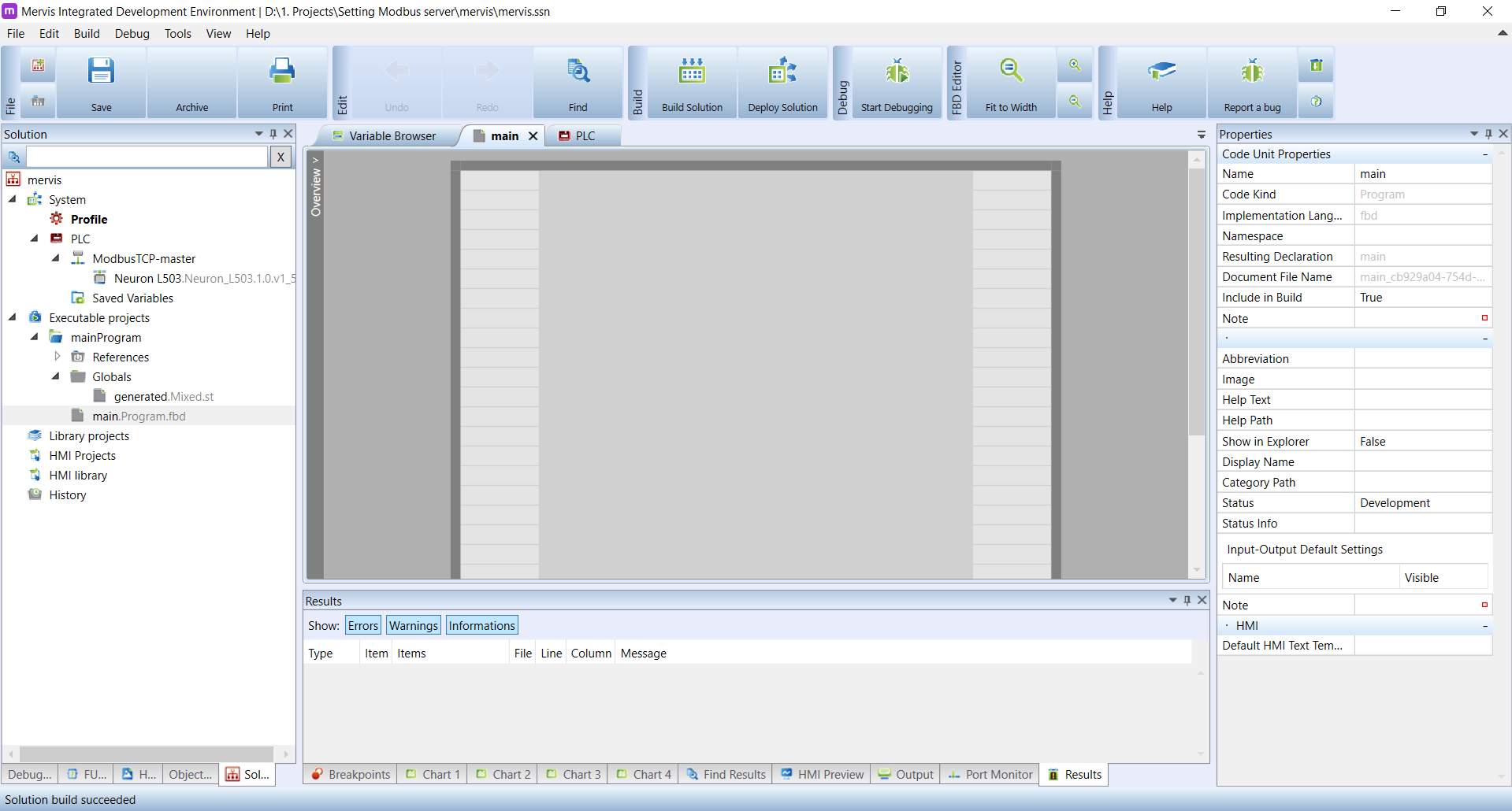
In our tutorial, we will use Unipi Neuron L503 which is equipped with two RS485 ports. Let's start with generic project in Full mode - attached PLC, one FBD program, configured task and set autogen on the Unipi device. Make sure, that the build and deploy works without any problem. Your workspace should look like this.
Now we need to add a Server channel. On the Left panel, right click on the PLC and in the context menu click on Add Server Channel.
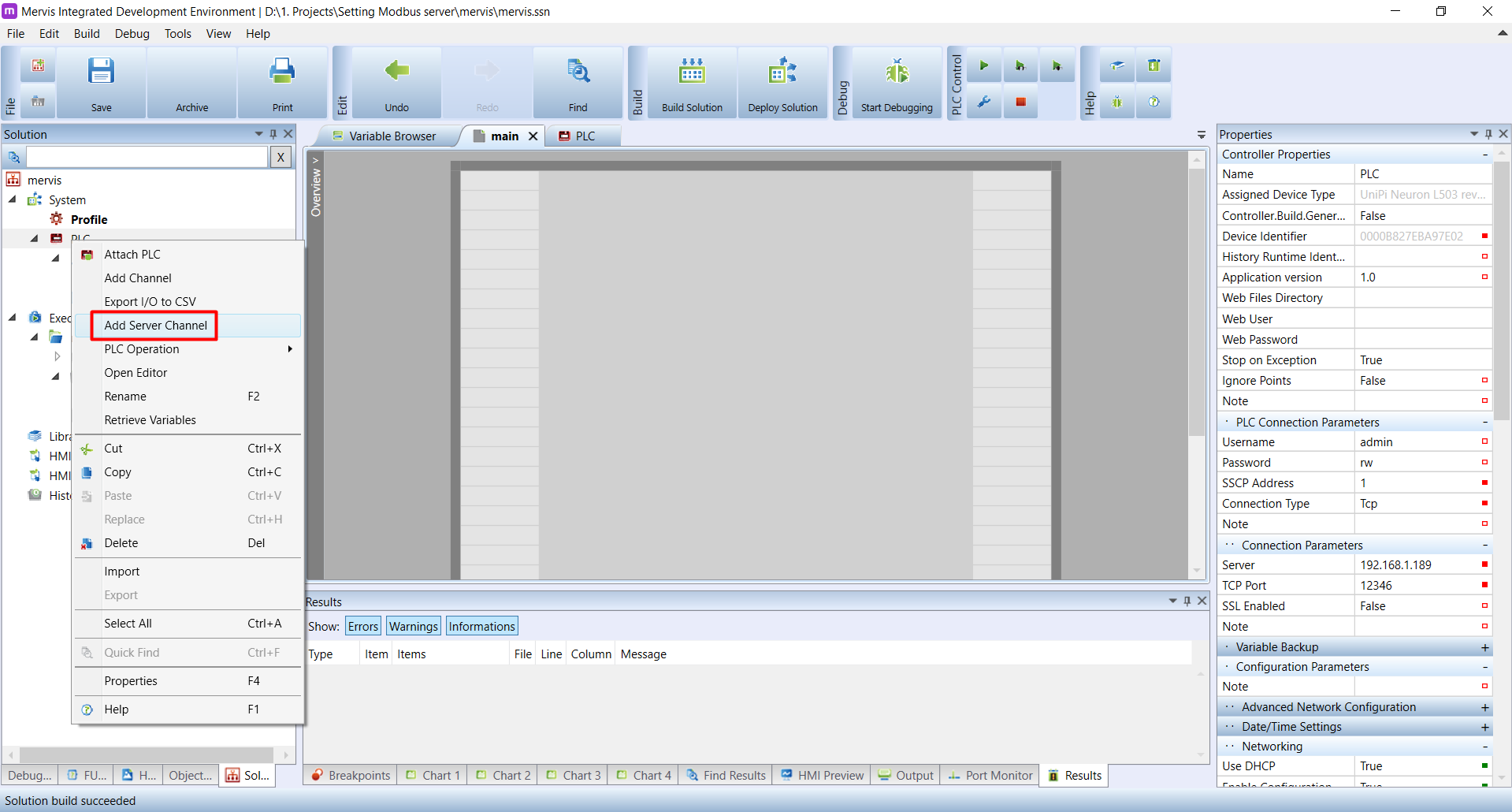
We are used to add channel, instead of server channel. Channel is for communication initated by Unipi controller. Server channel is for communication initiated by some other device to which the Unipi will respond to.
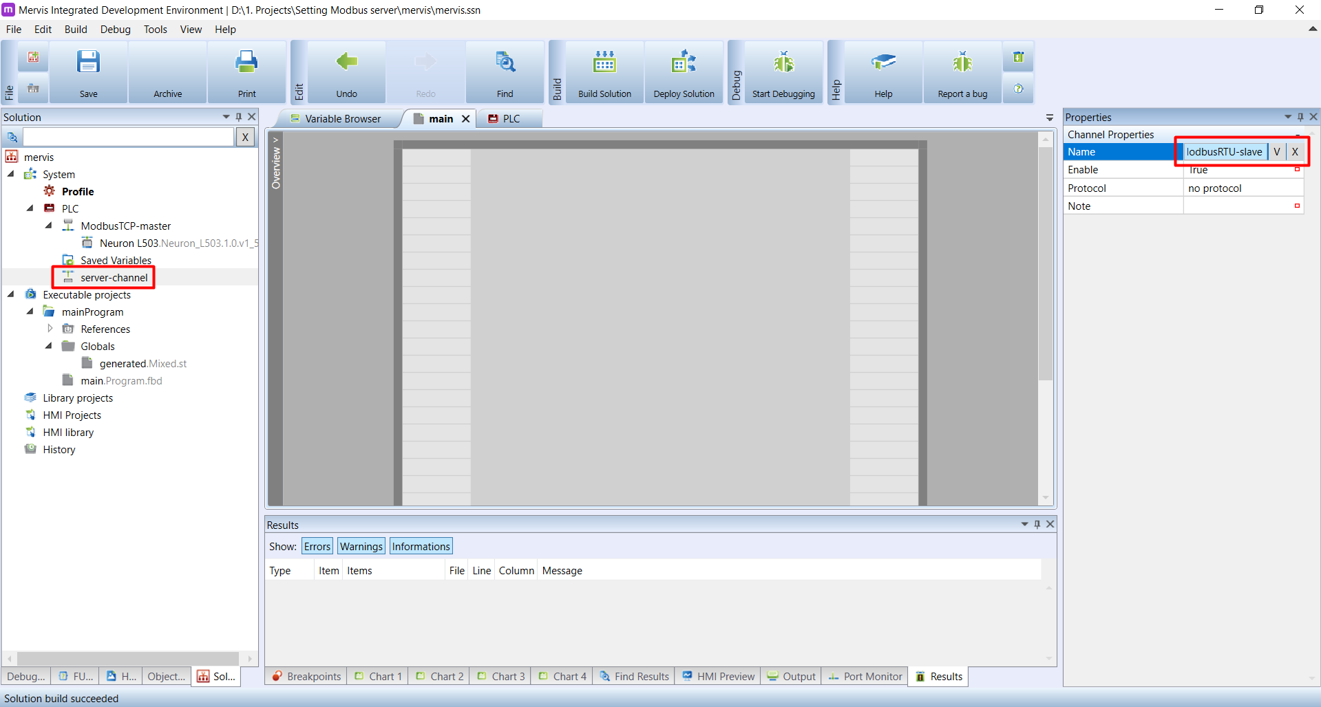
A new server-channel will appear under the PLC. Double click on it and on the Properties panel change the name to something more descriptive. The channel will be for ModbusRTU slave communication, so the name ModbusRTU-slave makes sense.
On the same panel, change the Protocol to ModbusServer.
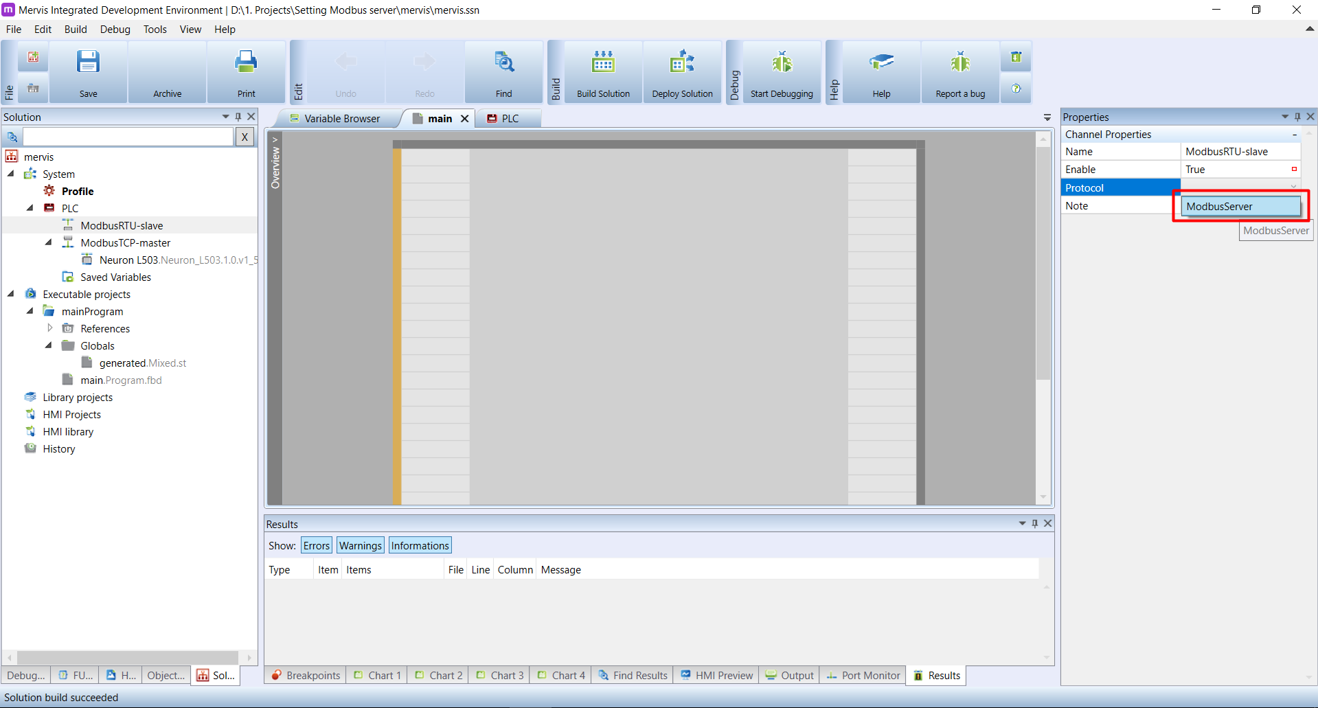
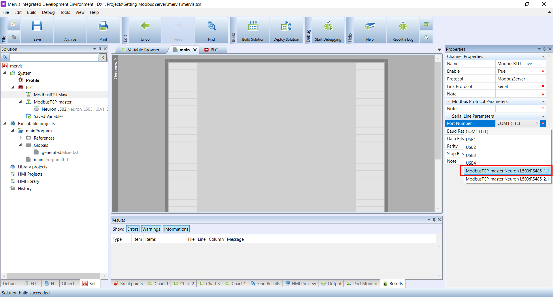
The Link Protocol is already selected to Serial. But we need to set the correct port.
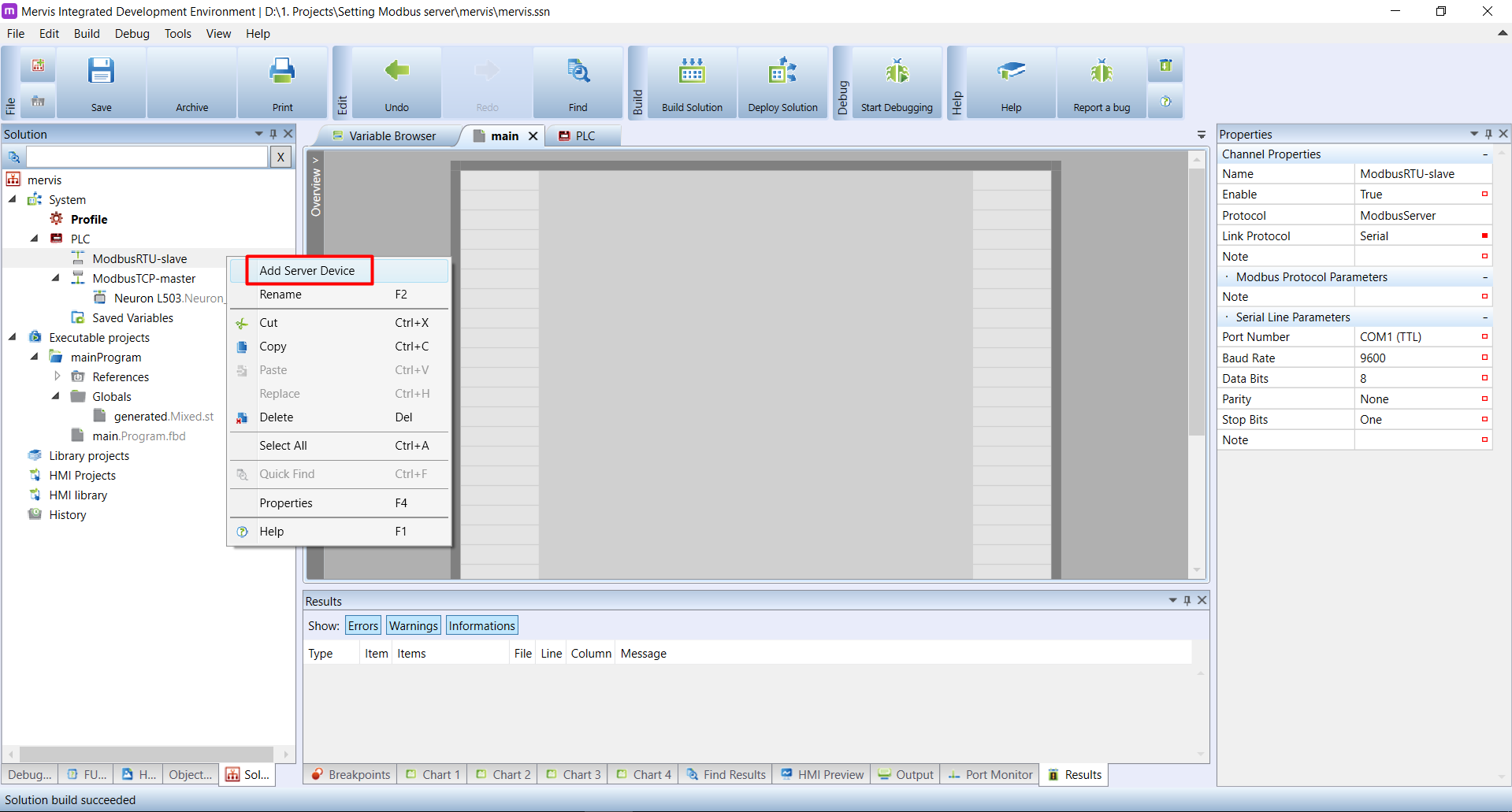
We have the channel configured, now we need to define some device. Right click on the channel name in the Left panel and in the context menu click on the Add Server Device.
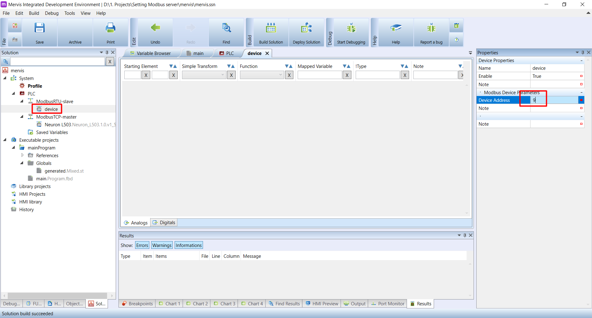
A new device will appear under the channel ModbusRTU-slave. Double click on it and in the Properties panel change the Device address to something meaningful. We could change the Name as well, but on this channel we will have only one device.
No we prepared everything we need to allow other devices to read and set variables in our PLC via ModbusRTU. The last thing is to define the Modbus registers and coil and their mapping to our variables. This will be the same for ModbusTCP server, so jump to the section Defining registers
Setting ModbusTCP server (slave)
Setting a ModbusTCP server (slave) is similar to the ModbusRTU server, but with different configuration of the server channel. Let's start with the same basic project. Your workspace should look like this.
Now we need to add a Server channel. On the Left panel, right click on the PLC and in the context menu click on Add Server Channel.
We are used to add channel, instead of server channel. Channel is for communication initated by Unipi controller. Server channel is for communication initiated by some other device to which the Unipi will respond to.
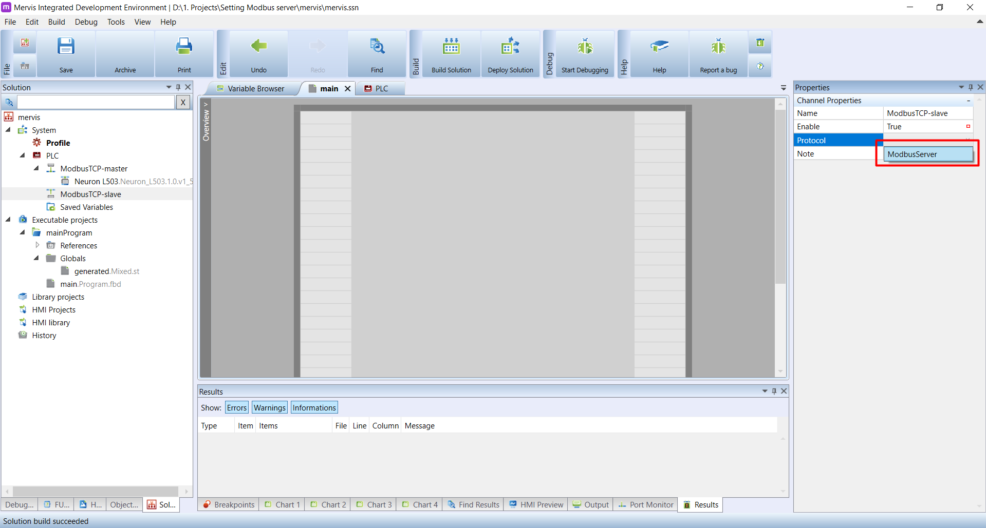
A new server-channel will appear under the PLC. Click on it and on the Properties panel change the name to something more descriptive. The channel will be for ModbusTCP slave communication, so the name ModbusTCP-slave makes sense.
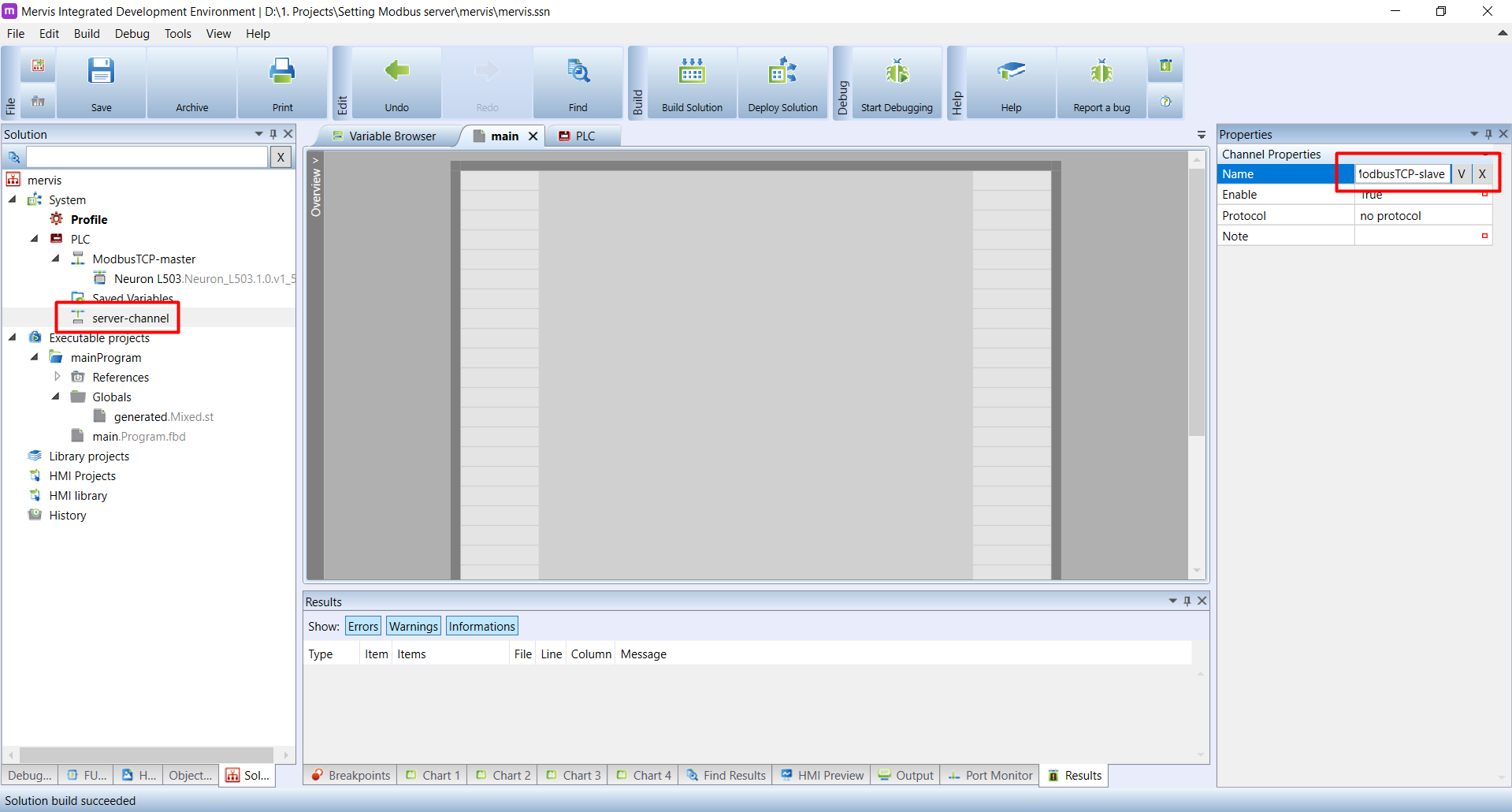
On the same panel, change the Protocol to ModbusServer.
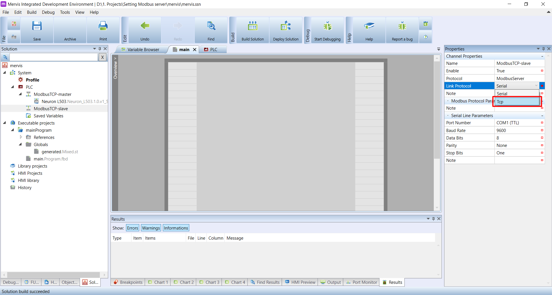
And in the Link Protocol select Tcp
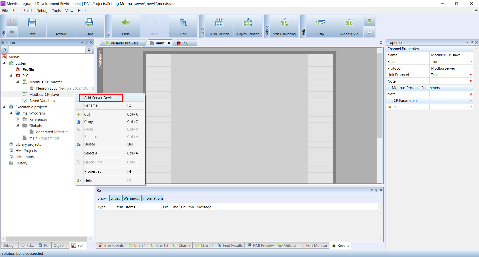
That's all for the Server channel settings, now we need to define the device. Right click on the ModbusTCP-slave channel on the Left panel and in the context menu click on the Add Server Device.
New device will appear under the channel ModbusTCP-slave. Select it and in the Properties panel, change the Device address to something meaningful.
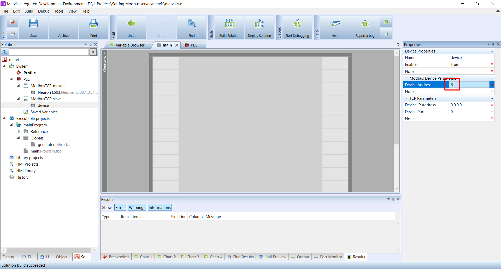
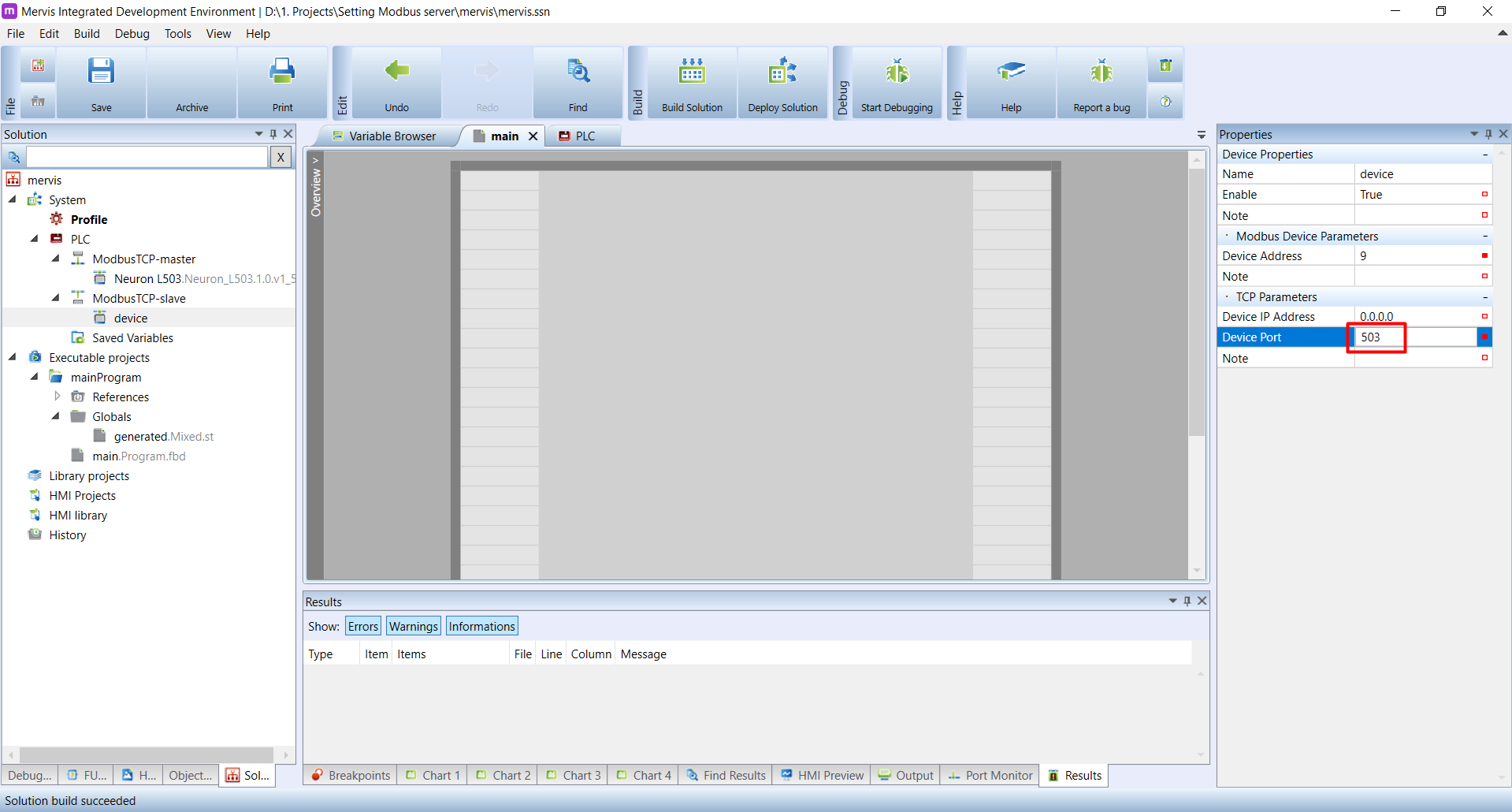
In the TCP Parameters section, you can see Device IP Address and Device Port.
You can leave the Device IP Address as is (0.0.0.0). The Mervis will internally set it to the current IP address of the PLC.
The Device Port however, you need to set. Typical ModbusTCP port is 502, but there is already running internal application on this port. So set it to 503 for example.
No we prepared everything we need to allow other devices to read and set variables in our PLC via ModbusTCP. The last thing is to define the Modbus registers and coil and their mapping to our variables.
Defining registers and coils
The Modbus communication is for exchanging data only. The master reads and sets datapoints configured in the slave. In Modbus, there are four types of datapoints you can read or write, but they have only two data types: boolean and word (16 bit integer). This is due to the age of the Modbus protocol (more than 40 years), and to keep the communication as simple as possible. Any other datatype (32 bit real, string,…) has to be converted to 16 bit value, for example by using more datapoints.
Datapoints
A “coil” is a boolean datapoint which the master can read and set its value. This datapoint is typically for controlling digital or relay outputs, which can only be set to TRUE or FALSE.
The second boolean datapoint is called “input” or “input status” and master can only read its value. Typically, you would use this datapoint for digital input.
The word datapoint is called “register” or “holding register” and master can read and set its value. You will use this datapoint for exchanging analog values.
The second word datapoint is called “input register” and master can only read its value. Typically, you would use this datapoint for reading a temperature.
Setting a datapoints
To set the datapoints, double click on the device under your Modbus slave channel in the Left panel.
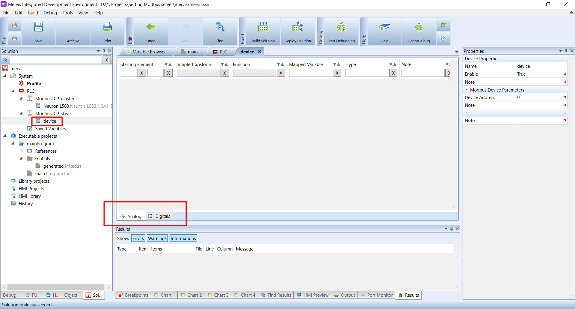
The list of registers exported by the device will appear in the Main window. At the bottom of the Main window, you can see tabs Analogs and Digitals. On the Analogs tab, you can manage the registers and input registers. On the Digitals tab, you can manage the coils nad inputs.
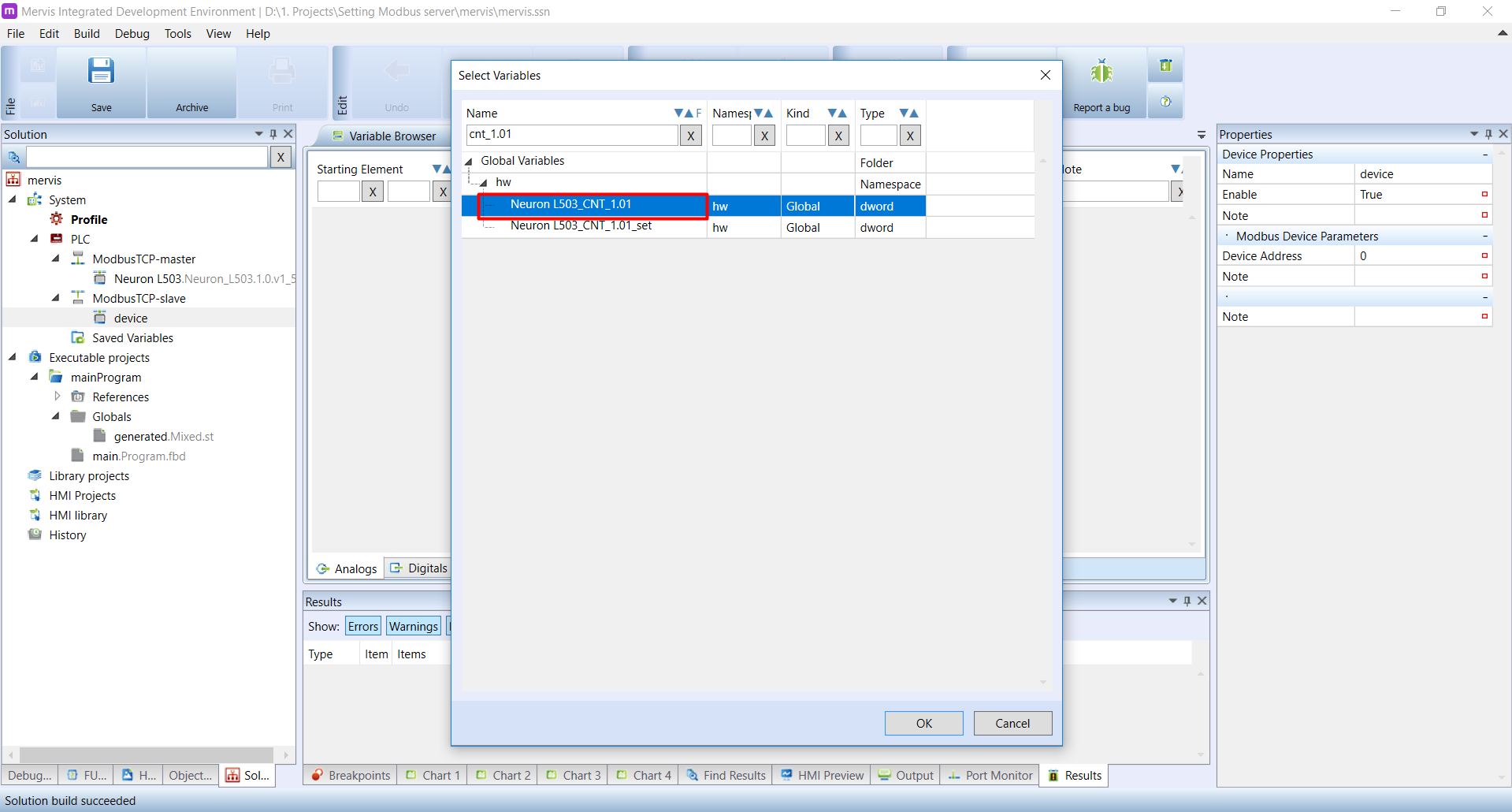
To add new register, right click on the empty list, and in the context menu, click on the Add Variable. This is the quicker way than selecting the Add Register.

The list of available variables will appear, and you can search in this list. Search for CNT_1.01 and select the Neuron_L503_CNT_1.01 variable, or the one with the similar name. An confirm by clicking on OK.
The new register will appear on the list. We can see it's properties:
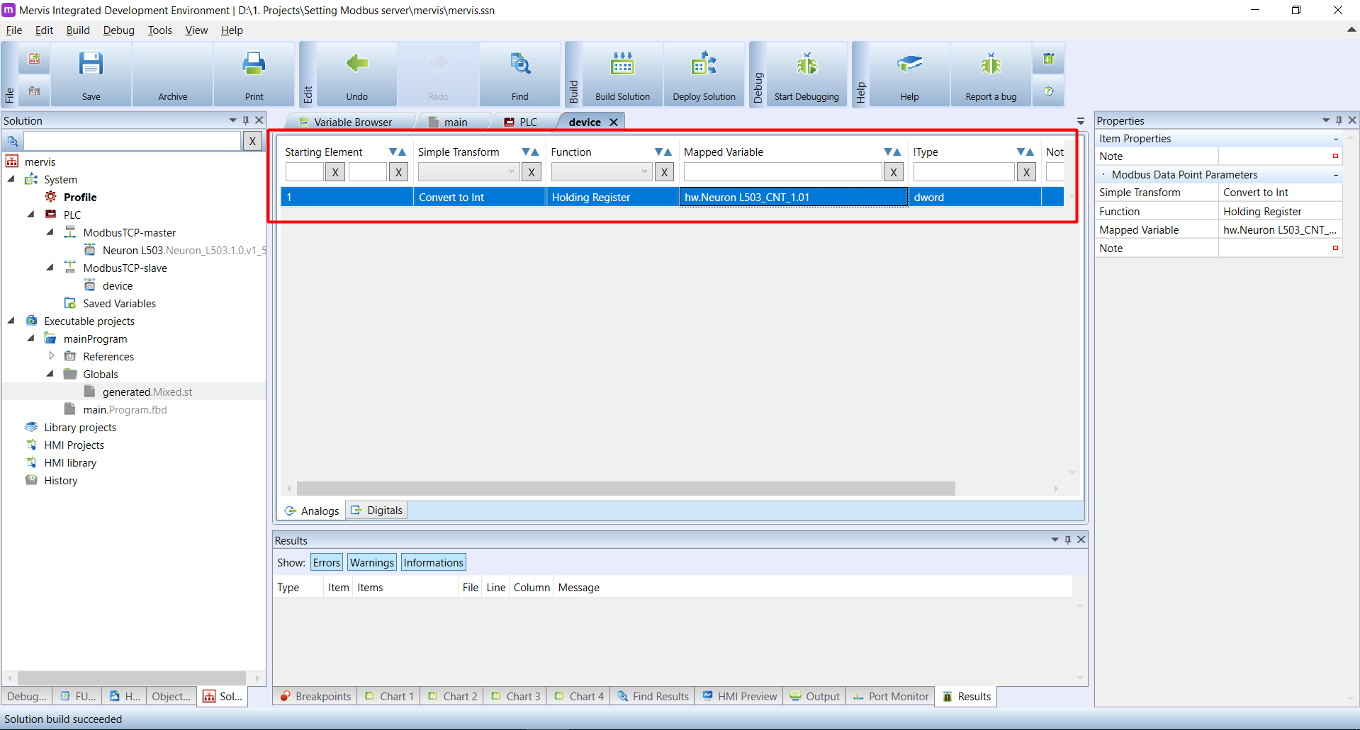
The properties are:
- Starting element is the address of the register. The address cannot be changed
- Simple transform offers a way how to transform the value from mapped variable to the Modbus register, e.g. convert to int, if the mapped variable is real
- Function is the Modbus function by which the register can be read
- Mapped variable contains name of the mapped variable
- Type shows the type of the mapped variable
To set the coils / inputs is practically the same, just proceed on the Digitals tab.