This is an old revision of the document!
Connecting to Modbus slave
One of the most common thing todo in industrial automation, is setting up the communication via Modbus.
Connecting to ModbusRTU slave
Let's assume you have a basic project in Full mode. You are attached to the controller, you have created Executable project with one FBD program and this program is set in PLC's Tasks. You also did a Set Autogen on the UniPi controller, and the Build and Deploy works without any problem.
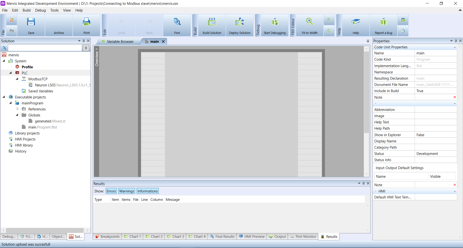
If you have done so, your workspace should look like this:
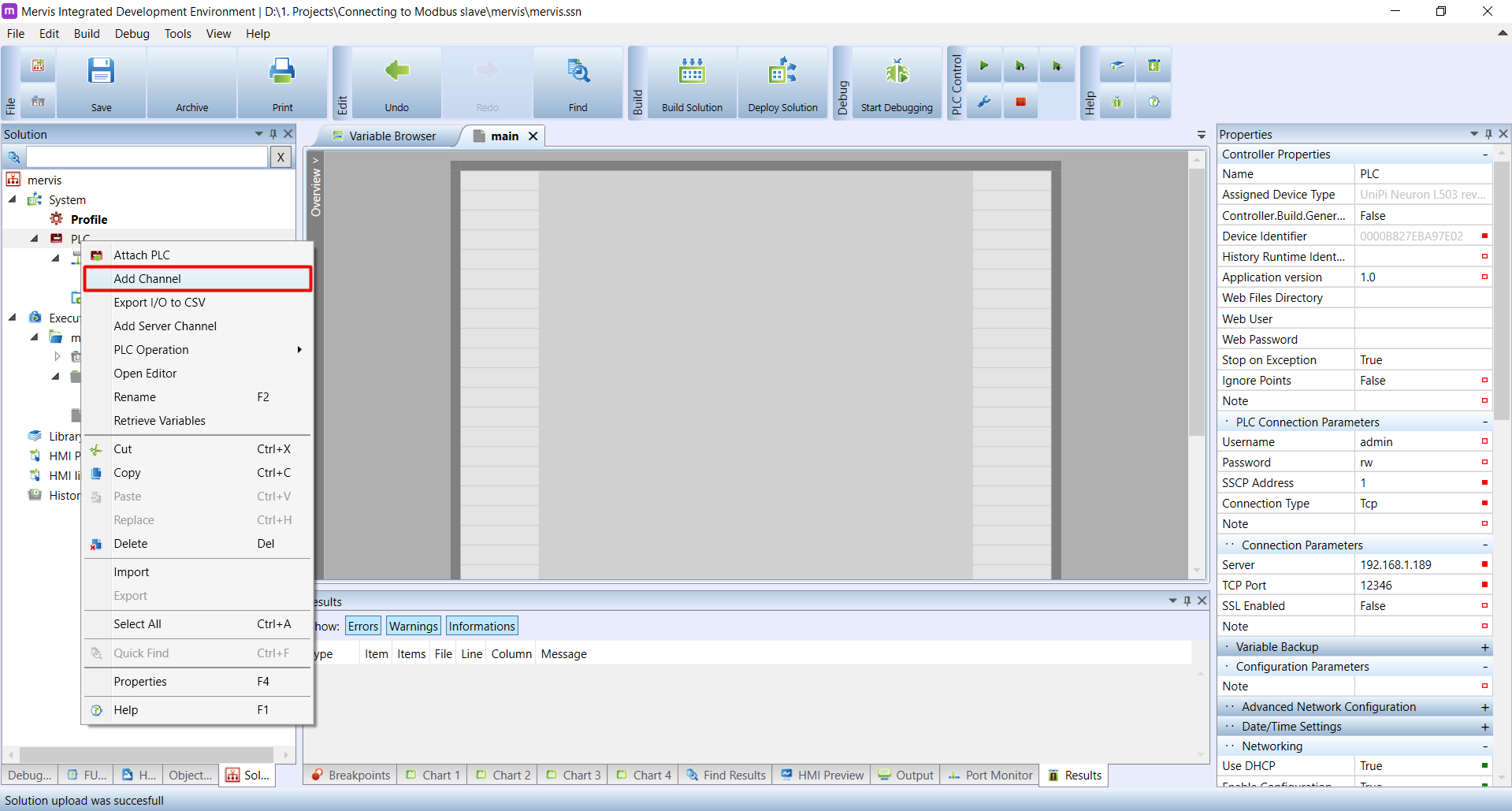
To set the communication via ModbusRTU, you need to create appropriate channel. Right click on PLC and in the context menu, click on Add Channel.
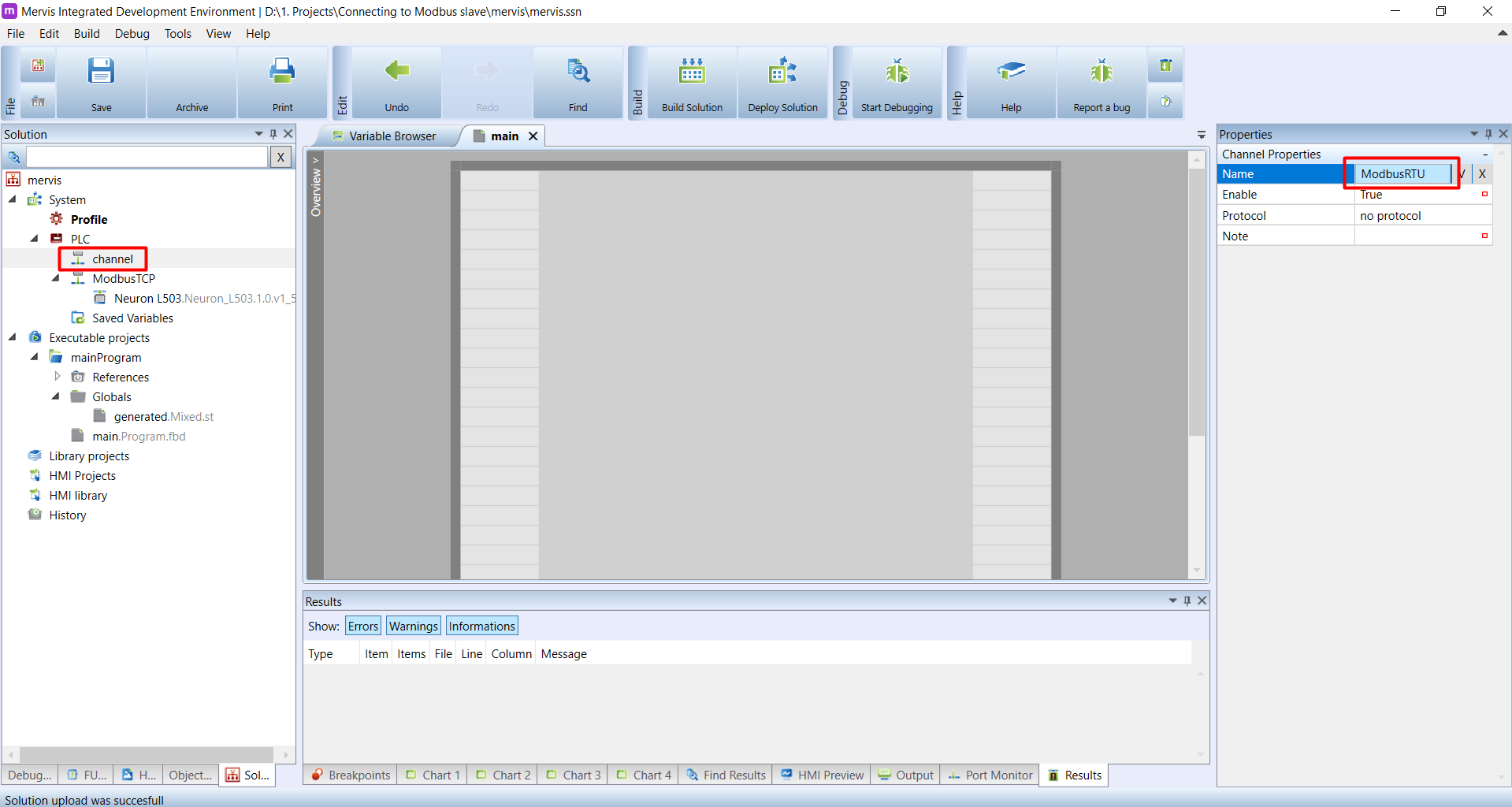
A new channel called Channel will appear under the PLC on the Left panel. Select it and in the Properties panel, change the name to something more descriptive. Since this channel will be for communication via ModbusRTU, the ModbusRTU is a good name.
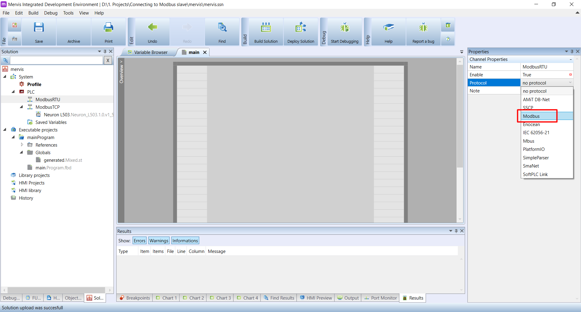
On the same panel, select Modbus protocol from the dropdown menu.
The default Link Protocol is set to Serial, so all you need to do, is to set the correct Serial Line Parameters. Pick the correct port from the Port Number dropdown.
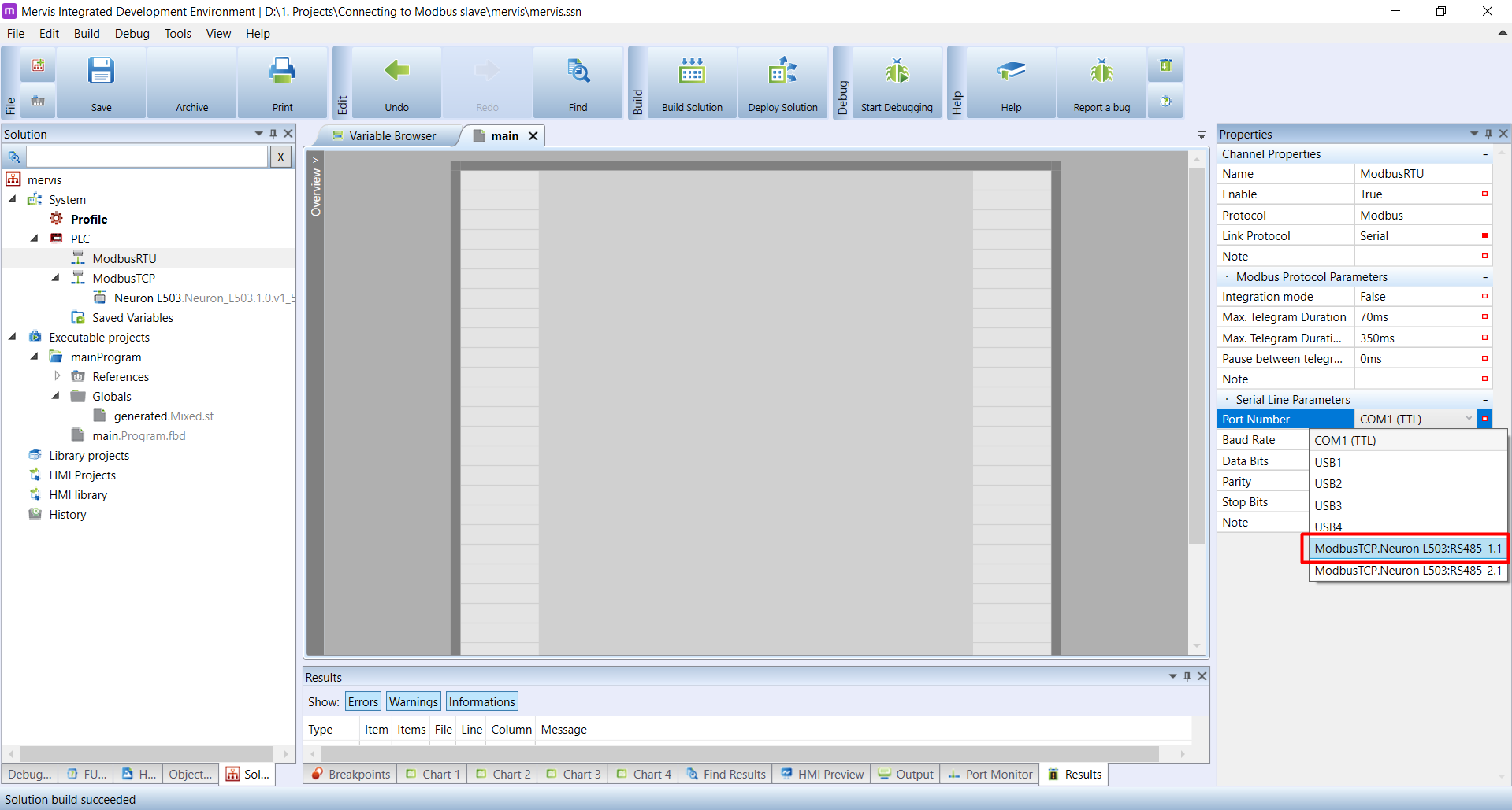
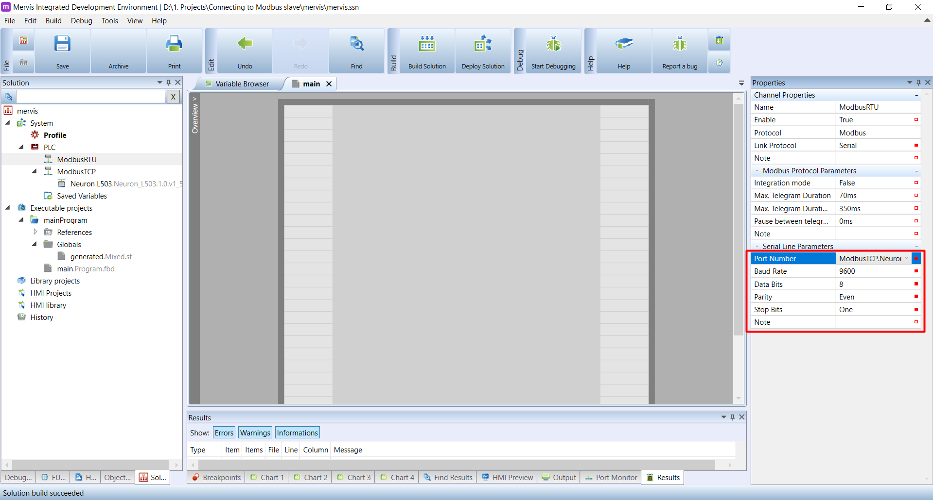
The rest of the Serial Line Parameters need to by exactly the same, as is configured on all the devices you have on the serial bus.
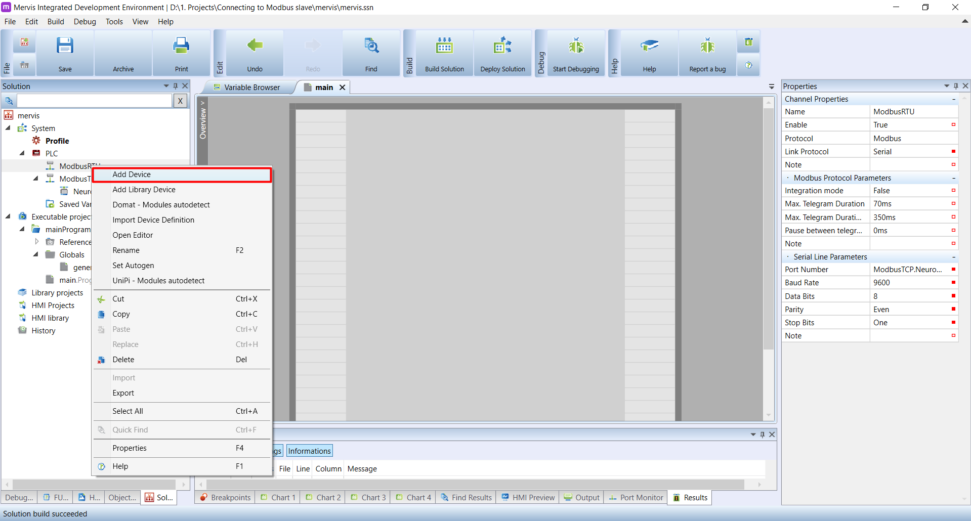
The ModbusRTU channel is configured and now we can add devices with which we want to communicate. Right click on the channel in the Left panel and in the context menu, select the Add Device.
A new device will appear under the channel. Select it and change its name in the Properties panel to something more descriptive. In this properties, you also need to enter the correct Modbus device address.
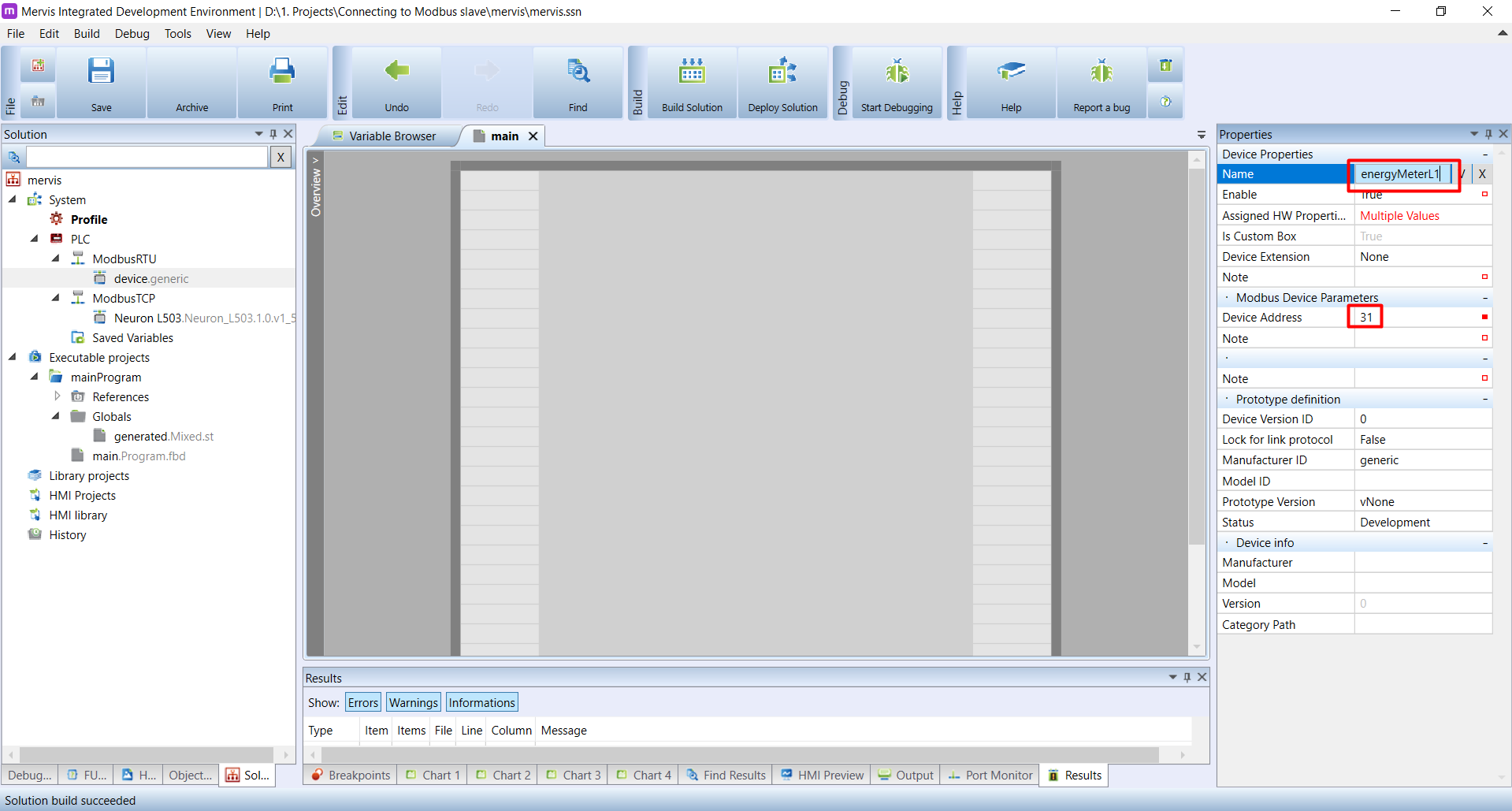
The name shouldn't be just the manufacturer's name and model, but rather the purpose or location of the device. If you have distribution box full of energy meters, it is better to name each energy meter by the circuit it is measuring, e.g. energyMeterL1.
The basic configuration of the ModbusRTU device is done, now we can dive into much more complicated stuff - the register map. Double click on the name of the newly added device. In the Main window an empty list of Modbus registers will appear.
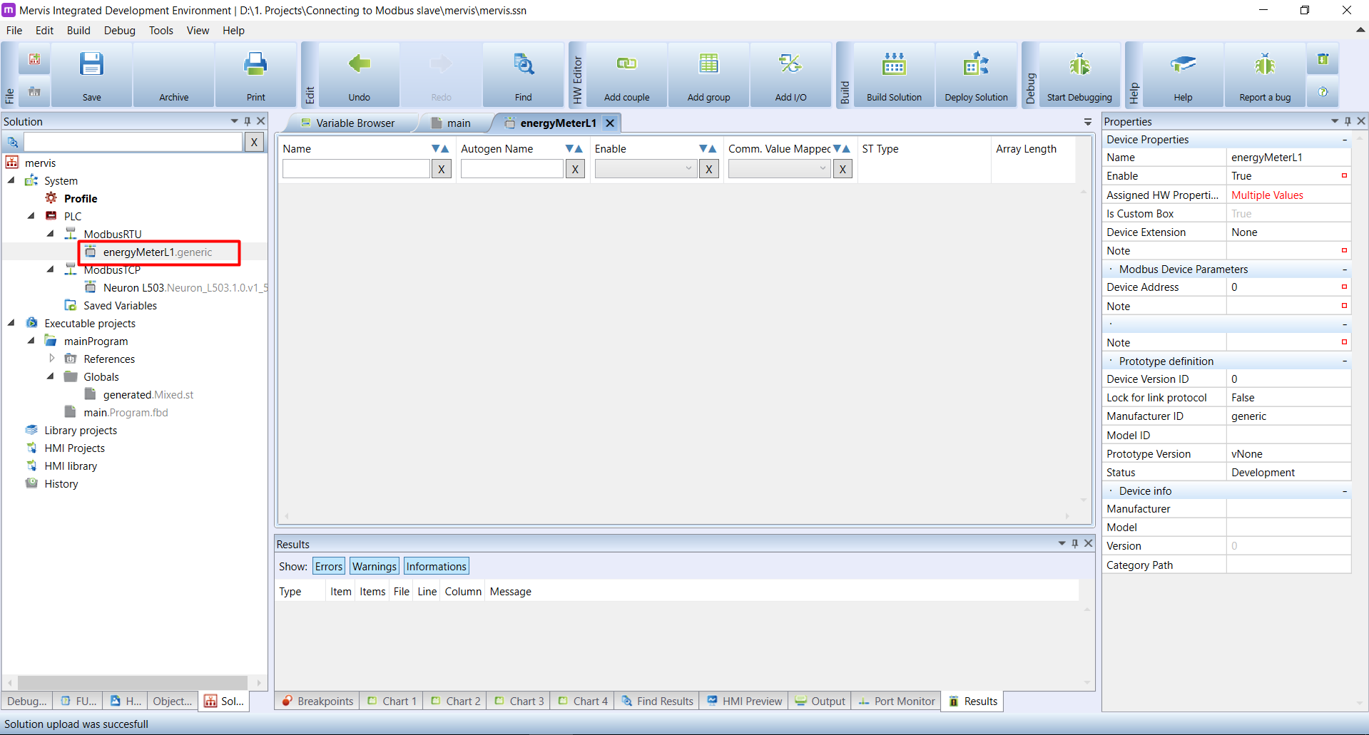
The values in Modbus slave devices are “shared” via registers (a strictly 16bit values) or coils (strictly 1bit statuses). In order to acquire these values from the slaves, we need to define, which registers we want to read and possibly, how to transform them into variables, which we can later use in our program.
It is time to introduce our ModbusRTU device, from which we want to read the data: The Inepro PRO1-Mod energy meter.
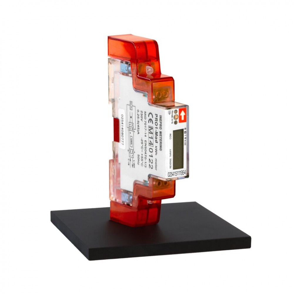
It is good thing to start with reading the manual. We already used an information from the manual - the speed and configuration of the serial line - 9600 bps with 8 data bits, even parity and 1 stop bit. The default Modbus ID is according to manual 1, but our meter has 31. In the manual, you can also find out how to get this number from the meter itself.
On the page 25 you can find the complete list of Modbus registers - their addresses, values and sizes. We will start with acquiring current voltage.

Unfortunately, this is where it starts to be really complicated, mostly due to the various ways of how the Modbus protocol is implemented by different vendors.
As you can see, the register's addresses are in hexadecimal format. You can't tell from the Voltage register, because the address of 5000 could be both in hexadecimal and decimal format. But if you take a look on the Current register, the value 500A clearly shows it is in hexadecimal format.
The Mervis IDE accepts only decimal values for Modbus registers, so you need to manually convert the ones from the manual, e.g. with calculator application in Windows or in MS Excel.
Another tricky part is the register's number vs. register's address. The register numbers start from 1, but register addresses start from 0. The Mervis IDE uses the register's number, but in the Inepro manual, they use register address.
To sum up both problems - the Voltage register's address is 5000 hexadecimal, which is 20480 in decimal and the register's number is 20481 (address + 1).
In many cases, it is hard to distinguish and reading a manual is simply not enough. You will have to resort to trial-and-error approach.


