This is an old revision of the document!
Communication and addressing
Modules can be configured using blue-white switches (HW configuration) placed next to the power connectors, or alternatively next to the RS485 on some models. Another option is configuration via Modbus registers (SW configuration). Configuration via DIP switches offers enough options for most applications, while configuration via Modbus registers provides broader possibilities (wider range of addresses and baudrates).


Please note:
The HW configuration is ideal for connecting and configuring multiple Extensions simultaneously.

Attention:
HW configuration of switches is read only at module startup (power connection, SW reset, Watchdog). HW configuration will be applied only when at least one address switch is in position 1, i.e. ON. If all address switches are in position 0, i.e. OFF, the SW configuration is read instead.
SW configuration via Modbus RTU
Default communication parameters (SW configuration)*:
- Number of data bits: 8 bits (fixed)
- Modbus address: 15
- Baudrate : 19200 bps
- Parity: None
Modbus register tables for Unipi Extension:
HW configuration using DIP switches
Each Unipi Extension features a set of blue-white switches.
Extension xS11, xS51, xS52, xS53, xS54:
These modules have 5 switches located next to the power connector at the module's bottom. The No.5 switch is closest to the power connector.
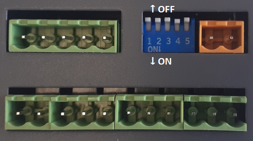
Switch:
- No.1 → Adress bit 1 (OFF - ignored, ON - value +1)
- No.2 → Adress bit 2 (OFF - ignored, ON - value +2)
- No.3 → Adress bit 3 (OFF - ignored, ON - value +4)
- No.4 → Bitrate selection (OFF - 19200, ON - 9600)
- No.5 → Parity selection (OFF - even, ON - none)
Extension xG18:
This module features 6 configurable switches located at the left bottom part. The switch No.6 is placed closest to the power connectors. The lone switch next to the RS485 connector serves to attach/detach terminal resistor, eg. cannot be used for configuration.

Switch:
- No.1 → Address bit 1 (OFF - ignored, ON - value +1)
- No.2 → Address bit 2 (OFF - ignored, ON - value +2)
- No.3 → Address bit 3 (OFF - ignored, ON - value +4)
- No.4 → Address bit 4 (OFF - ignored, ON - value +8)
- No.5 → Bitrate selection (OFF - 19200, ON - 9600)
- No.6 → Parity selection (OFF - even, ON - none)
Extension xS10, xS30, xS40:
These modules feature 8 switches located next to the RS485 connector at the upper part of the module. No.1 switch is closest to the RS485 connector.
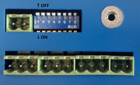
Switch:
- No.1 → Attaches/detaches the bus terminating resistor (not related to configuration)
- No.2 → Unused
- No.3 → Address bit 1 (OFF - ignored, ON - value +1)
- No.4 → Address bit 2 (OFF - ignored, ON - value +2)
- No.5 → Address bit 3 (OFF - ignored, ON - value +4)
- No.6 → Address bit 4 (OFF - ignored, ON - value +8)
- No.7 → Bitrate selection (OFF - 19200, ON - 9600)
- No.8 → Parity selection (OFF - even, ON - none)
Extension xS50:
Only 3 switches are available on this module, located between the power connector and the digital input terminals at the module's bottom. Switch No.3 is closest to the power connector.

Switch:
- No.1 → Address bit 1 (OFF - ignored, ON - value +1)
- No.2 → Address bit 2 (OFF - ignored, ON - value +2)
- No.3 → Address bit 3 (OFF - ignored, ON - value +4)
Please note:
If the HW address is set on xS50, the baudrate is always 19200 bps and even parity.


