This is an old revision of the document!
Analog inputs
If you are looking for information on the Extension xS52, xS53 and xS54, please see Analog inputs - type 2
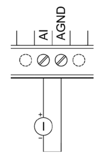
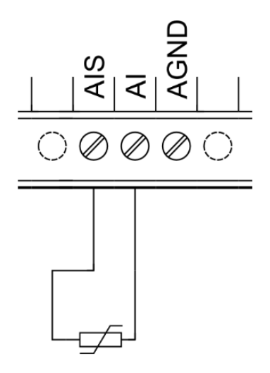
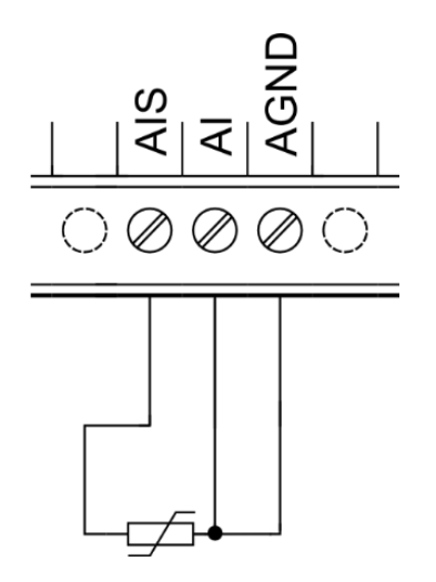
Analog inputs type 1 are available in the Extension xS51. To measure voltage or current, the negative pole of the external device to be measured is connected to the AGND terminal of the connector and its positive pole (signal) to the AIx (or AIy.x) terminal. The wiring for resistance measurement varies depending on the measurement mode.


Please note:
In its factory settings, the device is set to voltage measurement to prevent any potential damage of connected devices or sensors in case an unsuitable device/sensor is connected.

Attention:
Before connecting the measuring device, it is necessary to check measurement settings by the chosen software and according to the type of the connected device - see the measurement description below.
Connection
The following images illustrate the setup for measuring a voltage and current source on AI and AGND terminals.
Voltage measurement

Current measurement
Resistance sensors can be connected to analog inputs using a two-wire or three-wire method. The three-wire method holds the advantage of preventing measuring errors caused by the resistance of the used wire.
Two-wire method
Three-wire method
Mode description
Analog inputs on Extension xS51 can perform accurate measurements of current, voltage or resistance. Measurement mode needs to be set first in the control software. In voltage and resistance mode you can choose from two accuracy modes. The measured value is of float32 (real) data type and corresponds with the measured input value (V⎓, mA, Ω).
This type of analog input supports the following modes:
- 0–10 V⎓ voltage
- 0–2.5 V⎓ voltage
- 0–20 mA current
- 0–1960 Ω resistance (three-wire)
- 0–100 kΩ resistance (two-wire)
Special functions
Aside from the standard inputs and outputs, Unipi Extension modules also feature additional functions for broadening the possible applications, performance optimization and monitoring of the entire project. These functions are calculated directly by the Extension's microprocessor and are thus independent on the control software.
Default configuration
This function is used to save the current configuration of the section (extension module) into its memory. In the case of power cycle of the device or reboot of the section (extension module), the stored configuration is loaded and applied. This functionality is also known as “copy
running-config to startup-config”.
| Stored data | Default configuration |
|---|---|
| Measurement mode | voltage measurement |
Master Watchdog
This function runs on the section's (extension module's) microprocessor and continuously monitor the commands from the application running on the unit. If no commands are detected within a configured time (MWD Timeout), the section's (extension module's) processor automatically reboots and reverts to the default configuration described above. This function ensures a safe configuration is set in case of emergency situations (unit failure, communication error or software issues) to prevent damage to controlled devices or any hazards to personnel.
Technical parameters
| Input terminals | AI, AIS |
| Common conductor | AGND |
| Galvanic isolation | Yes |
| Input functions | 0–10 V⎓ voltage measurement, 0–20 mA current measurement, 0–1960 Ω or 0–100 kΩ resistance measurement |
| Resolution | 24 bits (resistance measurement), 16 bits (voltage and current measurement) |
| Conversion time | 400 ms (resistance measurement), 60 μs (voltage and current measurement) |
| Protection type | Integrated overvoltage protection |
| Maximum input voltage | 15 V⎓ |
| Measurement accuracy | ±0.2 % |
| Input resistance (voltage measurement) | 44 kΩ |
| Input resistance (current measurement) | 100 Ω |


