Multiple controllers in the Solution
When multiple PLCs need to be used on site, Mervis allows you to define multiple PLCs within a single solution. This is advantageous for clarity, speed of modification and project sustainability.
Solution must be in the Full mode, otherwise the option to add another PLC is not allowed.
Adding (another) controller to the Solution
Adding a controller to the solution is done by selecting the System line at the top of the left panel of the solution, right-clicking and selecting Add controller from the context menu. The PLC assignment is then identical to adding the first controller in simplified mode.

When creating the solution in simplified mode, a universal PLC definition is automatically created, to which the real PLC is then assigned. In the full mode, the PLC is always added identically, whether it is the first or nth PLCs.
PLC Names
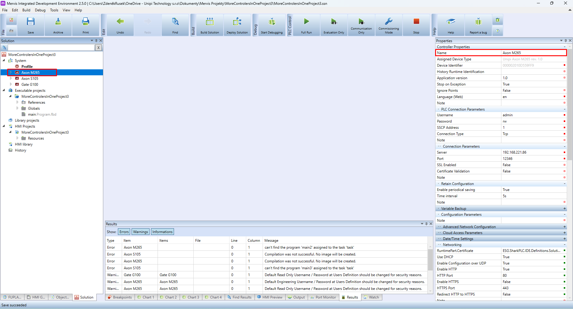
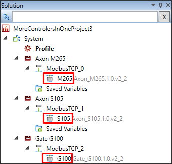
Mervis will generate the name of the newly added controller as PLC, PLC_0, PLC_1 etc. For clarity, it is very useful to change the controller name to a more descriptive one. This is done by changing it in Properties, which will be displayed in the right panel after the controller is selected in the Solution panel.
Main program and task definition
Every controller must execute a program. After adding a controller, it is necessary to define a task and map the program to be executed according to the set task parameters.
1. Creating a program
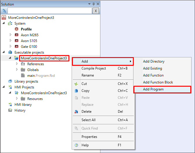
The program is created by selecting the name of the (executable) project, right-clicking and selecting Add > Add Program
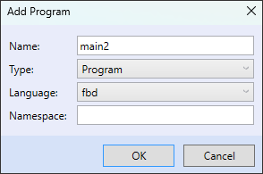
In the dialog box can be chosen the name of the new program and the language in which it will be written (FBD|ST). The type must be set to Program. For demonstration in this manual, one program will be created in FBD language for each PLC: main1, main2 and main3.
Before the next step, it is necessary to compile the solution so that the newly created programs are included in the solution and can be assigned (mapped) to the task.
The compilation result will be unsuccessful, the reason is a missing task for the newly added PLC.
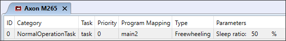
2. Creating and configuring a task
The task is created by right-clicking anywhere in the window area that opens after double-clicking the name of the desired PLC.

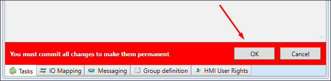
All changes must be confirmed by clicking OK in the red bar.
Double click in the box under Program Mapping to open the dialog table. In this table, the desired program is selected with the mouse and added by clicking the Add → button.

The default task settings remain.
Detailed task creation, settings, program mapping are described in a separate article.
Solution structure
As the solution gets larger, it is advisable to choose the right names and structure. Otherwise, the solution will be chaotic, increasing the chance of mistakes and making it much harder to get an overview after some time.
If autogen is used to generate the variables of the connected devices (expansion modules, sensors, etc.), it is important to choose device names based on the PLC name, HW type and other details that specify the location and usage as much as possible. The reason for choosing such names is that the device name is part of the name of the variable generated by autogen. The title should consist of a few abbreviations (2-4 characters) separated by an underscore and should not be very long.
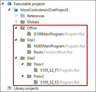
The directory structure of programs should correspond to logical and physical structure.
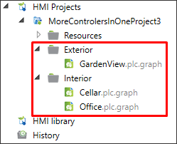
The structure in HMI projects should be organized according to a similar logic.
Debugging
If there are multiple controllers in the soluton, debugging is a bit more complicated. When you start debugging, you need to select which PLCs to debug (which IDE connects to) and have the correct PLC selected when debugging, in case multiple PLCs are running the same program.
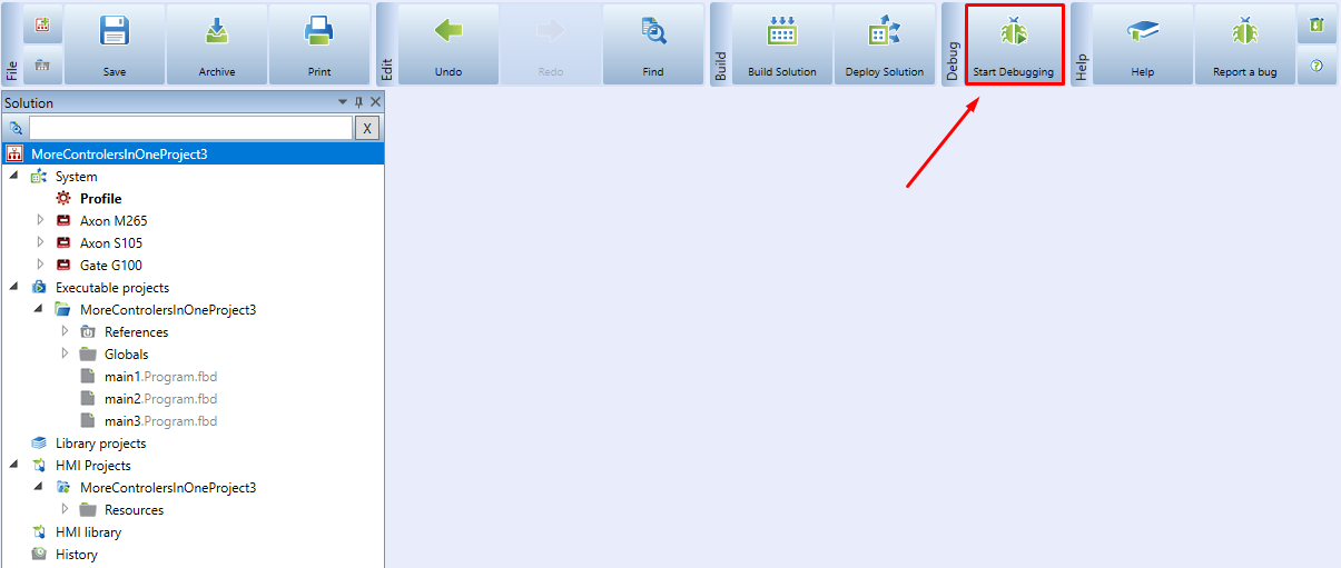
The debug is activated by clicking on the Start Debugging icon with a green bug image on the ribbon.
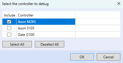
Next, it is necessary to select one or more controllers to work with in the debug mode and confirm by clicking OK.
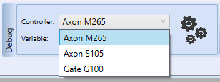
When debugging, it is also necessary to select the desired controller in the drop-down menu, in the Debugging section on the ribbon.
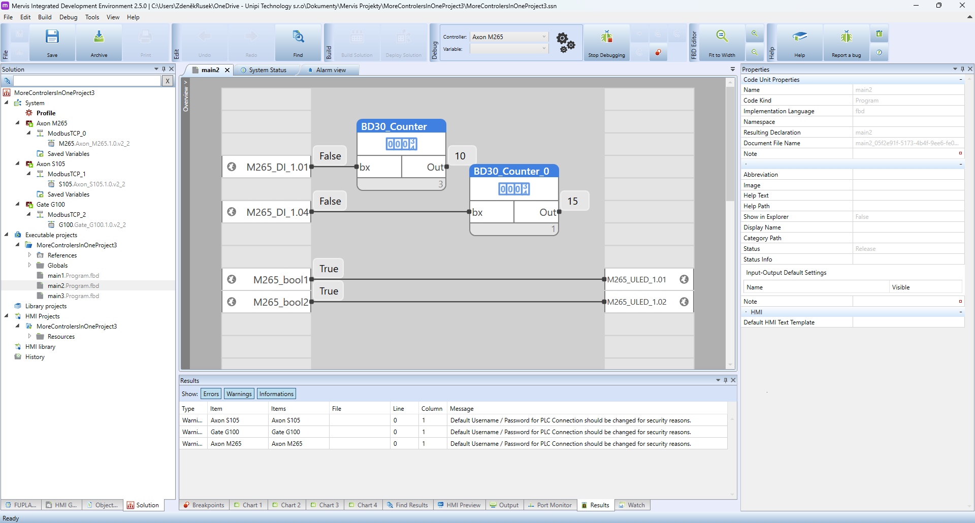
The debugging will then look something like this. For this demonstration, two BD30 function blocks, several variables and autogen was used.
Options with multiple PLCs
Adding multiple PLCs to a single solution opens a number of options that can be deployed more easily. The whole solution is clearer, easier to understand and debugging is much easier.
Using multiple controllers in a solution:
- placed in distant locations, with LTE internet connectivity, monitoring and controlling parts of a large area, but within a single project. In this case, the Mervis IDE connects to the PLCs via Proxy and communication between PLCs can be via SSCP protocol (also via proxy)
- that are part of medium-sized installations where each PLC controls a separate part (heating, HVAC, access control, control of individual machines, etc.)
- is ideal for creating and deploying a central SCADA monitoring and control, or external webserver