Connecting Mervis IDE to Weintek HMI device using the BACnet/IP protocol
If you need to connect the Mervis IDE and the HMI display using a local network, you can use the BACnet protocol. For your project, you can use the HMI, in this case, the Weintek touchscreen HMI display, for system control, production control, boiler control, home control, etc.
Patron
Neuron
Gate
Unipi 1.1
Axon
In the following tutorial, you will learn how to set up a BACnet server, how to connect to the server with a client, or how to generate a list of variables (.EDE file).
The result of this tutorial is to show the PLC inputs as controls on the HMI display and to control the PLC digital outputs directly from the HMI display.
About BACnet
- The protocol uses Client-Server model
- The client access data via server-side objects (A/D values, trend logs etc.)
Prerequisites:
- Unipi PLC with Mervis OS v2.2.0 or newer
- 24 V⎓ power supply for the Unipi PLC
- Local network connectivity (switch or router)
- 2× RJ45 network cable
- EasyBuilder PRO program (also contains a simulator)
- Weintek HMI display with Ethernet, or Weintek HMI simulator
- + 24 V⎓ power supply for the HMI display
- + 1× network patch (RJ45) cable for the HMI display
Useful additional info:
- Creating a new project in the Mervis IDE
- Yet Another BACnet Explorer (YABE) – a software to access BACnet network
- A Modbus guide for connecting the HMI to a Unipi PLC with Mervis OS
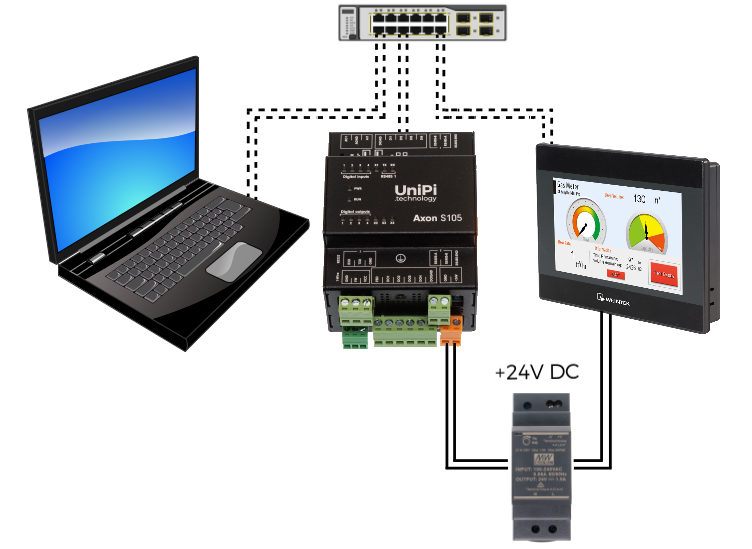
Connection example:
1 Basic Mervis IDE settings
Create a new Mervis IDE project or open an already existing project. Follow the following guide:
Create a server channel by right-clicking on PLC and choosing Add Server Channel. Name the new channel BACnet_server.

Select the newly created BACnet_server and set the protocol type to BACnetServer.

Right-click on the BACnet_server server channel and choose Add Server Device.

Name the newly created device BACnet_UDP. Select the device and set the same parameters in Properties in as following:
- Device instance: 1 (1-4194302, unique within the network)
- Management Password: set your password
- IP Address: 0.0.0.0
- Device Port: 47808

We are almost done now. Click on Build Solution.

2 Variables, mapping and linking
Next step is to create BACnet objects and link them to a local or global variable. This step is very important to allow the client to read or write to variables. There are 2 ways to do this:
Note: It is possible to link unused variables to BACnet objects. However, Mervis IDE will warn you that server variables could not be loaded, and that image could not be created. The reason is the variable is not used for compilation and the BACnet object thus does not have any variable to link to.
2.1 Variables, mapping and linking
Click on the BACnet_UDP device and then right-click into the blank space. A pop-up menu will appear – choose Add Variable.

A drop-down variable list will appear. Choose a variable you wish to read or write to via the Weintek HMI.

A BACnet server variable will become available. Click on Build Solution in order to generate BACnet object parameters (identifier, type, etc…) – until now, these were displayed only as n/a.

The result should look like this. You now have your first BACnet object including its ID.

2.2 The alternative way: directly through the Variable Browser
In the Variable Browser look up the variable you want to make available for the BACnet server to read from/write to, and check the PLC:BACnet visible checkbox.

A drop-down menu will appear. In PLC: BACnet Device, choose the BACnet device you want to make the variable available for. In our case the tab will be pre-filled with BACnet_UDP. Check the following picture for reference:

If you now click on the BACnet_UDP device, the Mervis IDE should display all previously selected objects.

Now click on Build Solution. By doing so the BACnet object parameters will update and new parameters will be generated.

The result for adding two objects should look like this:

You can now deploy the solution by clicking on Deploy Solution. All changes you made will be uploaded into the PLC.

3 EDE file export (optional step)
EDE files are useful if your BACnet client is unable to automatically detect objects on the BACnet server, or if you want to set up client device without access to BACnet server.
Right-click on BACnet_server and choose Export EDE file.
You will need these files to import the variable settings into the client, so the display will know which variables it should read or write to. Any exported EDE files can be found in the /“Project_Name“/export subfolder.

Examples of exported EDE files:

4 EasyBuilder PRO settings, simulator/HMI download
Download, install and run the EasyBuilder PRO software tool.

Create a new project for your HMI display model. If you don’t have the HMI display, you can choose the MT6071iP/MT8071iP as on the picture below.

Upon creating the new project, a System Parameter Settings</html> will appear. Click on New device/server.

A new window with several additional settings will appear. Enter the following parameters:
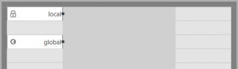
- Name: BACnet/IP (Device)
- Location: local
- Device type: BACnet/IP
- I/F: Ethernet
Now click on the Settings... button.

In this tab you can set up the IP address either manually, or you can click on Who Is… and the server will be found and set up automatically. The standard BACnet port is 47808 – if you selected a different port in Mervis IDE, you need to change the BACnet port here as well.
Caution: Make sure that no other application is listening on the same port on your PC. If it would listen on the same port, the Who Is… option would be unable to find any servers and the simulation would not communicate with the BACnet server.

Confirm all changes and click on the newly created BACnet/IP tab. Then click on Tag Manager….

Now click on Get Tag Info… to automatically download objects from the BACnet server (Mervis). If the variable info cannot be downloaded, please check if the port is not already used.

Select BACnet objects you wish to use – in our case select everything. Confirm all changes and close the settings window:

You should now see an empty HMI window which is used to insert various graphics elements.

Let’s test it by creating a single Toggle Switch and a single Bit Lamp The Tag tab serves for object mapping..

In the list you can see objects available on the Unipi PLC. Please choose a DO for Toggle Switch. Then look up the hw_$Axon S105_DO_1_01_w$ object and select PresentValue.

For Bit lamp choose one of the DI variables.
Look up the hw_$Axon S105_DO_1_01_w$ object and select PresentValue.

The result should look like this.
Note the displayed info about which BACnet object is linked to the graphics element.

Now click on Compile.

Upon compilation you can now either load the HMI project into the HMI display, or you can start the simulator.
- If you have HMI display, click on Download (PC -> HMI)
- If you want to use the simulator, click on Online Simulation
Note: The Offline simulation option cannot be used, as the simulation would not be able to connect to the PLC.

5 Result
Now check the HMI or the simulation. You can see that the state of DI1 is being displayed on the Bit lamp object which glows blue when the DI is active. Also, by clicking on the Toggle switch, you can switch the value of DO1.

Check the PLC’s LED indicators. If you followed all steps and the communication is running OK, states of DI1 and DO1 on the PLC presented by the LEDs will correspond to the states on the HMI/simulation.