This is an old revision of the document!
Advanced task definition
In the Mervis system, it is possible to define the tasks to be run in the PLC (RT). A task is a definition of conditions for running a selected / mapped program or several different programs in a specified order.
In the simple mode of the project, one task is always defined that repeatedly executes the main.program.fbd program and this cannot be changed. If the need arises to have multiple PLCs in one assembly, to run multiple different programs, or to condition the execution of a program, it is necessary to have solution in the in full mode.
This guide describes how and where to define tasks, what categories and types of tasks exist, including how to achieve optimized program execution, error handling, their logging and eventually self-repair.
Defining a task
After the solution is generated in simplified mode, a task is automatically created for the PLC with a mapped main program. When the solution is created in full mode, the task must be created and the program mapped.
To add a task, simply right click anywhere in the open window and then select Add task from the context menu.

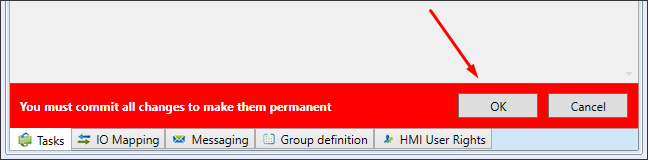
Task creation and any modification must be confirmed by clicking OK in the red bar.
Warning!
All changes to the task must always be confirmed by clicking OK in the red bar.
Task properties description
Double-clicking the PLC name in the Solution will display a list of defined tasks with their properties.
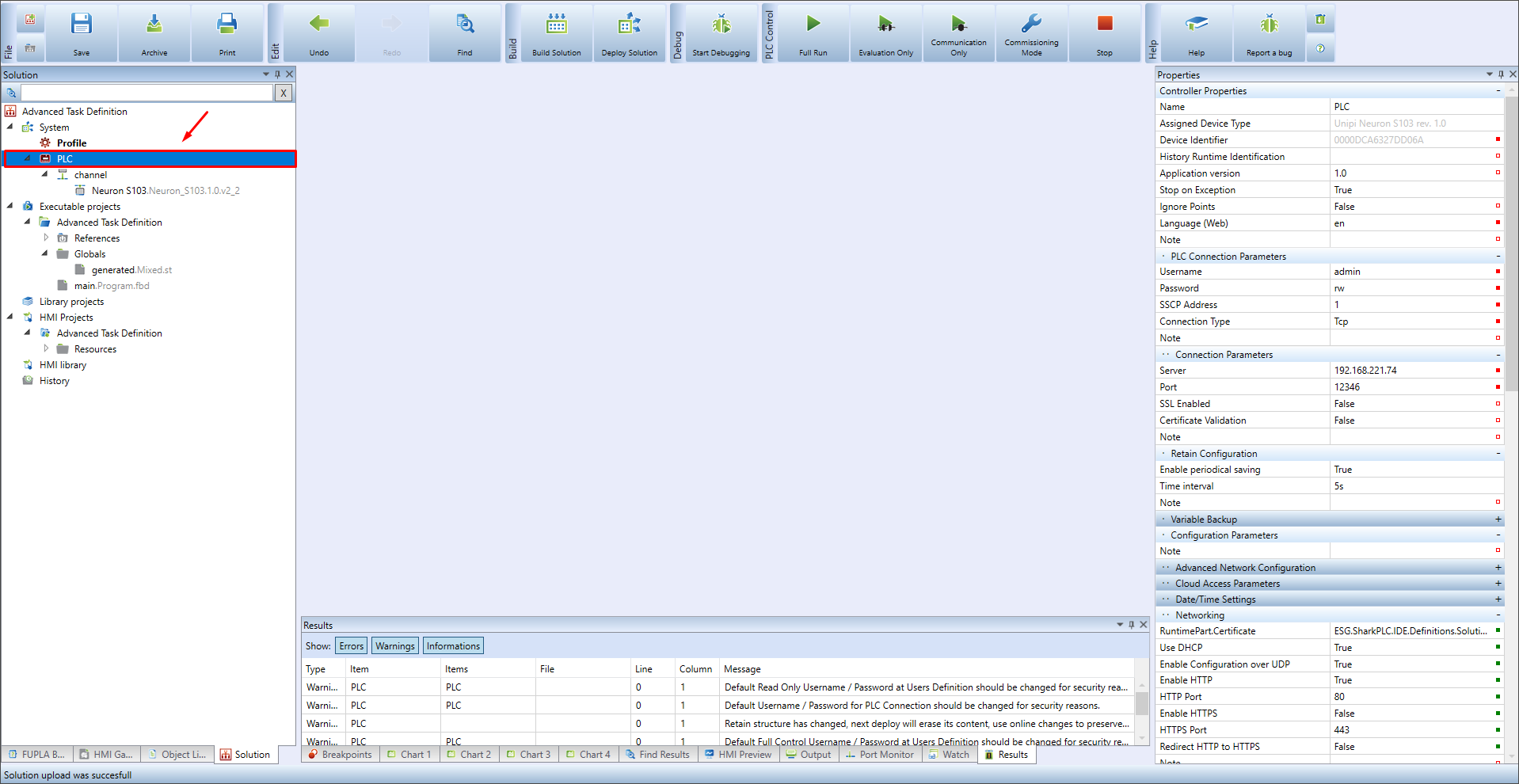
The default state of the PLC tasks list (creation in Simplified mode):

Tasks have the following properties:
| Properties | Meaning |
|---|---|
| ID | Task identification number |
| Category | Task category, described in Task categories |
| Task | Custom task name |
| Priority | Priority, with which the task will be executed, zero being the highest priority |
| Program Mapping | Assigning a specific program to a task |
| Type | Type of task run, described in Task types |
| Parameters | Parameters vary depending on the type used |
Task categories
There are four categories of tasks, but only two are used:

NormalOperationTask - Normal operation, default option for every task. The task runs according to the specified type and parameters
ExecutionError - Triggers in case of a critical NormalOperationTask error (e.g. division by zero). If a job with this category is created, the job ID is automatically changed to the last (highest) ID. There can be only one job with this category.
Mervis IDE allows you to create multiple NormalOperationTask categories, provided that the first one is of the Freewheeling type, or Cyclic and the other tasks in this category will be of type Event only. The task types are described in detail below.
Program mapping
By clicking in the box under Program Mapping the table will be displayed:

In this table, desired program is selected by clicking on it and added by clicking the Add → button.

If the desired program is not displayed in the list, you need to compile the solution.
Task types
Task type defines the way of its execution.

| Type | Meaning |
|---|---|
| Freewheeling | Normal execution, pause between cycles according to % setting |
| Cyclic | The task is started periodically according to the defined interval in ms |
| Event | The task is executed if the defined condition is met |
1. Freewheeling
Setting the Freewheeling type means that the selected task will be executed over and over again, according to the PLC's capabilities. The Sleep Ratio parameter specifies the time to wait for the next computation cycle. The time is given as a fraction of the time of the last computation cycle. Example: if one computation cycle takes 10 ms and Sleep Ratio will be set to 30%, controller will run the next cycle after 3 ms.
2. Cyclic
If the Cyclic type is set, the job will be executed every fixed period [ms]. For longer periods, it is convenient to use the ST syntax, for example, when setting a period of 2 h and 30 min, we write the value “t#2h30m” instead of the number “8400000” (data type TIME).
3. Event
The Event setting offers conditional execution of a task that can be executed either once or repeatedly in response to a selected variable. There are 4 options in total:
| Trigger condition | Meaning |
|---|---|
| Rising Edge | Single task execution at the rising edge |
| Falling Edge | Single task execution on the falling edge |
| High Level | Continuous task execution at TRUE value |
| Low Level | Continuous task execution at FALSE value |

After expanding the variable parameter, a table with a list of variables appears, the desired variable can be added by selecting it and clicking the Add button.

If you want to use *commerror variables, you must use it in the main program - it is enough to connect it to itself, otherwise even will not be ran.

Example of use
Setting the safe state of the controlled device
Safe values are those that cannot endanger the life and health of the worker or damage the equipment. If an exception occurs during program execution (e.g. division by zero), NormalOperation will be stopped and the ExecutionError task will be started.
1. Example of a safe condition of the device "Sawmill"
The device operating the saw. When a program error occurs, the NormalOperation task is stopped and the ExecutionError task is started, which stops the saw blade and feed. This error condition treatment avoids potential injury to workers or saw damage.
2. Example of a safe condition of the equipment "Cement Plant"
Equipment operating a filler in a cement plant. When a program error occurs, the NormalOperation task stops and the ExecutionError task starts, which closes the bin flaps. This error condition treatment avoids unnecessary material loss.
NOTE It is good practice to set the default values of the I/O boards to safe values.
After error condition is taken care of, to restart the NormalOperationTask task it is necessary to put the RESUMENORMALTASK function into the ExecutionError task.
Notification by email/SMS, or optically signalling fault by ULED
It is possible/appropriate to inform the relevant persons about the error condition by email/SMS and to record this condition by triggering an alarm. A detailed description of the notification settings can be found in the separate articles about email-sending and SMS respectively.
For illustration, it is possible to add optical signalling e.g. on the user LED X1, or to switch the DO/RO output with a connected signalling device.
Usage of Event type
1. Starting a single action
On a rising edge of the DI single action will be called - affecting a program parameter, sending a report, or calculating a new value based on the event.
2. Switching between two programs
Depending on the value of a DI, two different programs will be executed (false program1 and true program2). This is useful mainly for FBD, as in ST you can get the same behavior by using IF condition.
3. Executing programs with defined time period
Block BD2 (pulse generator) will generate pulses, which could execute another program. It's convenient to use in cases, in which we need to repeatedly run another program, but undesirable to run every computation cycle (to save up computational performance).


