Connecting M-Bus devices
Mervis IDE also implements the M-Bus (Meter Bus) protocol, which is the European standard for remote readings from electricity meters, gas meters, water meters, etc. It communicates at slower speeds from 300 to 9600 bps (most often 2400 bps), but this is fully sufficient for normal meter reading purposes. The maximum total bus length is from 350 to 1000 m, depending on the selected communication speed. The maximum number of meters depends on the converter used and the total amount of data read.


Attention:
It is necessary to understand the difference between the M-Bus communication protocol and the physical M-Bus communication interface:
- Communication protocol: Data are transferred in frames that contain information about the address, message type, and values to be transferred. Frames are composed of bytes (8-bit). The protocol also allows writing and some connected devices to be configured in this way.
- Physical interface: Two-wire bus for communication and power supply of connected meters. Due to its communication principle, it is possible to choose almost any wiring topology (and combinations) as long as it reduces the total bus length. Circular topology is not allowed!
Attention:
When using an RS-485/M-Bus converter, communication is half-duplex and is not guaranteed to be compatible with all connected meters. If the meter does not respect the standard and responds to queries too early, the RS-485 communication direction will not switch from transmit to receive and the message from the meter will not arrive in full, or at all. The solution is to use a converter on the RS-232 bus, which is (fully) duplex.
Prerequisites
The M-Bus communication protocol is available in Mervis IDE for all Unipi controllers. Unipi controllers that are not equipped with a physical M-Bus interface must be used with a suitable converter.

Note:
An example of such a device are RS485/M-Bus converters available in the Unipi e-shop. However, other physical interface converters can also be used, e.g. RS232/M-Bus.
Follow the documentation of the converter when connecting to the controller. Connecting the meter to the M-Bus is easy as it does not depend on polarity and you can therefore connect the meter in any way you like.
Communication channel
The following steps require that you have already created a Mervis IDE solution with an attached controller and connected an M-Bus converter with at least one M-Bus meter.
To create a new communication channel, right-click on the PLC and select “Add Channel”:

Highlight the newly created channel by mouse click, in the right column select “Protocol: M-Bus” and set the “Serial Line Parameters” according to the parameters of the connected M-Bus meter:

Note:
The communication parameters of the meter can be obtained in the meter documentation, directly in the meter interface, or with a special tool of the meter manufacturer (software + reading head).
After creating and setting up the communication channel, it is necessary to “Deploy Solution” to the controller.
Add Device
It is possible to define the device manually, but this is time-consuming, difficult and error-prone. It is also possible to add a device from a library, but after the implementation of the automatic device creation tool, the library development was discontinued. Therefore, the preferred method is to automatically find and create a meter definition directly from the physical device.
After deploying the solution, the M-Bus channel is created in the PLC and the meter search can be started. Right-click on the M-Bus channel and select “Search for M-Bus meters in the network”:

Note:
If you know the address of the device, you can skip the search by selecting “Create M-Bus Meter From Real Device”.
Confirm the entry into Commissioning Mode (beware! it interrupts the program), select the address type, or modify the range of addresses to be searched, and start detection by clicking “Next”:

If the detection was not successful (e.g. due to bad wiring), you can repeat the action by clicking the “Back” button to return to the previous step.
When M-Bus meters are successfully detected, a list of meters is displayed, where each row represents one meter. The first column “Import” can be ignored, on the other hand, the important column “Create” is used to import and create the device definition at the same time. The other columns indicate the primary and secondary addresses, the meter manufacturer, or the meter type.
To add them to the solution, select the desired meters in the “Create” column and click the “Next” button:

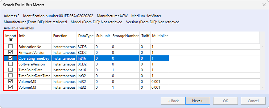
For each selected device, the device import dialog box opens with the selection of individual registers.
Note:
The more registers are imported (communicated), the longer the interval between reading the same register.
Change primary address
It is also possible to change the primary address within the M-Bus meter search dialog. To change the address, it is necessary to search for the meters according to the procedure above and when the list of meters is shown, just mark the row with the meter and then set the new address:

Attention:
after change of the address it is not possible to create the meter immediately, but it is necessary to return to the previous step by the “Back” button and search for the M-Bus meters again.
Conclusion
Resulting device/meter definition:

In full mode of the solution, it is now necessary to generate variables for the data points. The procedure is described in the article about Autogen.
Further details, such as manually defining or modifying communication, are available in the Mervis IDE Help (F1).


