This is an old revision of the document!
LED indication
This article contains the description of LED indication, all device states and a device startup simulator.
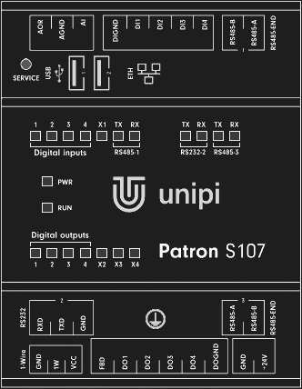
Patron
Description of LED indicators
| Label | Function | Meaning | Colour |
|---|---|---|---|
| PWR | On | Supply voltage indication | Red |
| RUN | Blinking | Microprocessor I/O status indication | Green |
| Digital inputs (DI) | On | Indication of log.1 at the input | Green |
| Digital outputs (DO) | On | Output switch indication | Green |
| Realy outputs (RO) | On | Relay switch indication | Green |
| TX (RS485/RS232) | On | Indication of serial line broadcasting | Green |
| RX (RS485/RS232) | On | Indication of serial line receiving | Green |
| User LEDs | Selectable | Freely programmable user LEDs | Green |
The following chapters describe all LED states for the Unipi Patron controller:
- Normal startup
- Run in service mode
- Upload/Backup OS
- Regular functions - communication via serial lines, DirectSwitch, MasterWatchDog
- FW update on I/O boards
Next to the state description is a picture showing the status of LED indicators.
Some states can have several meanings and can mean e.g., a computer module error or an inappropriately chosen method of communication. You will find everything in the description of individual states.
Description of the individual device states
All LEDs are off
State:
Power-Off
The controller power supply is unplugged. The controller power supply is unplugged. If the PWR LED does not change its stateon the controller even after connecting the power supply, try another power supply. If the state does not change after replacing the power supply, it is likely that the controller has been damaged. In this case, please contact technical support.
PWR is On
State:
Power-On
The controller is powered. If the controller remains in this state longer than a minute without change, it is possible that it is damage. In this case, please contact technical support.

PWR is On and RUN blink slowly
State:
Does not communicate with I/O
RUN LED:
ON: 2000ms / OFF: 2000ms
If communication with I/O is not required and the web page of the controller can be displayed, or the device responds to the response test (ping), this is a regular operating state.
By default, this state is indicated when the program in the controller is not communicating with the I/O board. The state, for M and L controllers, is indicated for each section separately by means of a RUN LED with the corresponding marking (RUN1, RUN2, RUN3).
Because the default program in the controller does not communicate with I/O, it is also the default state when starting the device after purchase.
If the controller is not visible in the local network and this condition is indicated, it may be a fault in the computing module. Try flashing OS, if this fails, please contact technical support.


PWR is On, RUN is On with short blinks
State:
Communicates with I/O
RUN LED:
ON: 2000ms / OFF: 50ms
The main computing module (Zulu) communicates with the input and output (I/O) board of the given section. Communication can take place via Modbus TCP server, SysFS method, file entry or using API EVOK.
By default, this status is indicated when a program in the controller is running and communicating with the I/O section.
PWR is On, RUN is On with short blinks, TX and RX are blinking
State:
RS485 traffic
TX/RX LED:
randomly blinking
The program in the controller communicates via a serial line RS485-1.

PWR is On, RUN is Off and the rest is blinking
State:
Service mode
Blinking speed:
ON: 600ms / OFF: 600ms
Controller is in service mode.
PWR is On, RUN is Off and the rest is blinking rapidly
State:
Flashing/Backup
Blinking speed:
ON: 80ms / OFF: 80ms
Indication of flashing or backup of OS.

Description of special states of the controller
DirectSwitch function
The DirectSwitch function is implemented directly in the micro-processor of the I/O section and is therefore independent of the control SW i.e., also of communication with inputs and outputs. You can read more about this function in the article about description of inputs and outputs. The function can be configured in one of three modes, their short description and illustrative LED indication can be found below:
DirectSwitch Copy
Input state is copied to the output.

DirectSwitch Inverse-copy
Negated state of the input is set on the output.
DirectSwitch Toggle
If a rising edge is detected on the input, the output state is negated.

Master Watchdog
If the function is enabled on the microprocessor of the given section, the processor continuously monitors the communication from the computing module. If no commands are detected during the set time, the section processor automatically restarts and sets the saved default configuration. You can read more about this function in the article about description of inputs and outputs.
I/O board firmware update
When flashing FW I/O board, all LEDs in the top and bottom row are On, except for every fourth. LEDs that are not fitted are also included in this rule.
Completion of the update is indicated by turning On every second LED and subsequent restart of the I/O section is indicated by turning On all LEDs, including RUN.

Controller startup modes
The Unipi Patron controller can run in two modes. In theregular and in the service mode. Each of these modes is indicated by a specific blinking of the LEDs. Below we provide a controller startup simulator, where you can see the entire process from plugging in power to startup. The simulation also shows the status of the SERVICE button for a mode other than regular. The simulation can be started by pressing the “Plug in power” button below the controller image.
In regular mode
Observe the RUN LED during regular startup. After plugging in the power supply, the OS boot loader “uboot” starts first, this state is signaled by the first longer turn On of the diode. After a while, the OS will start.
Startup without I/O communication:
The controller is ready if the RUN LED blinks constantly slowly.
| Behaviour description | Meaning | Off | On | |
|---|---|---|---|---|
| PWR is on, RUN is on with short blinks | OS is running but not communicating with I/O board | 2000ms | 2000ms |
Spuštění s programem včetně komunikace s I/O:
Kontrolér je připraven, pokud dioda RUN trvale svítí a opakovaně na krátkou dobu pohasíná.
| Popis chování | Význam | Nesvítí | Svítí | |
|---|---|---|---|---|
| Svítí PWR, RUN svítí a krátce pohasíná | OS běží a komunikuje s deskou I/O | 50ms | 2000ms |
V servisním módu
Hledáte-li návod pro vstup a práci v servisním módu, pokračujte na tento článek.
Tlačítko SERVICE je sepnuto a drženo před připojením napájení, poté sledujte diodu RUN. Po připojení napájení nejprve startuje zavaděč OS “uboot”, tento stav je signalizován prvním delším rozsvícením diody. Přibližně 5 vteřin po připojení napájení je možné tlačítko SERVICE pustit. Po chvíli začne startovat OS.
Následně se spustí servisní mód signalizovaný pomalým blikáním všech diod, kromě PWR a RUN.
| Popis chování | Význam | Nesvítí | Svítí | |
|---|---|---|---|---|
| Svítí PWR, RUN nesvítí a ostatní pomalu blikají | Kontrolér je v servisním módu | 600ms | 600ms |
Speciální funkce servisního módu - nahrání OS z USB
Hledáte-li návod pro nahrání OS z USB, pokračujte na tento článek.
USB disk je připojen, tlačítko SERVICE je sepnuto a drženo před připojením napájení. Následné stavy LED a tlačítka jsou shodné se servisním módem až do spuštění OS.
Poté se spustí nahrávání OS signalizované velmi rychlým blikáním všech diod, kromě PWR a RUN. Po dokončení se kontrolér restartuje.
| Popis chování | Význam | Nesvítí | Svítí |
|---|---|---|---|
| Svítí PWR, RUN nesvítí a ostatní rychle blikají | Nahrávání OS | 80ms | 80ms |