Relay outputs are terminated on terminals labelled by a switch schematic sign and serve for switching two-state devices with alternating or current voltage. The COM terminal is common, serving as input for switching voltage. NO and NC terminals are used as the switching voltage output.
NO - in the default state (no voltage), contacts are open
NC - in the default state (no voltage), contacts are closed
The state (On/Off) of each relay is indicated by a LED with a corresponding label. Overload and overvoltage protection should be provided externally by a circuit breaker (ideally one for each output). Nominal current and circuit breaker type should be selected according to the load and its characteristics concerning the maximum current on the output.
Warning:
If an inductive load is connected (e.g., electric motors, relay coils, contactors, or even the cables in extensive electric installations), it is necessary to protect the relay outputs with a corresponding external element (e.g., varistor, RC circuit or a suitable diode).
If a capacitive load is connected (e.g., power sources of LED lights), it is necessary to protect the relay contacts against inrush current by connecting a corresponding thermistor to the relay's output.
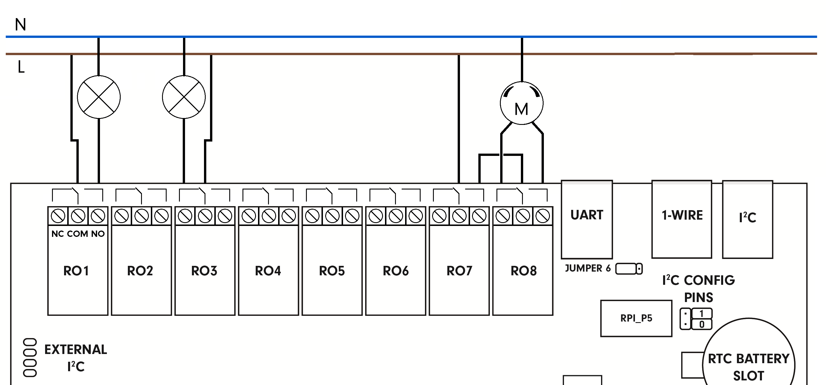
Connection
The following image depicts the connection of ohmic (resistance)load with alternating voltage and connection of a three-way valve to Unipi 1.1 relay outputs:
Technical parameters
The data below represent a selection of the most important parameters and serve only as a quick reference.
 Detailed information can be found in the product datasheet provided by the relay manufacturer:
Finder 36.11.9.005.4011
| Output type | Electromechanic non-shielded relay |
| Designation on the board | RELAYx (where x represents the relay number) |
| Number of terminals per relay | 3 |
| Terminal designation | Schematic (on the board) |
| Common terminal (COM) | Middle terminal |
| Closed without voltage (NC) | Terminal engaged according to scheme |
| Open without voltage (NO) | Terminal disengaged according to scheme |
| Contact/Output type | Switchable NO/NC (SPDT) |
| Number and type of relays | 8 × Finder 36.11.9.005.4011 |
| Switching voltage | 250 V AC
30 V DC |
| Max. switching current (resistive load) | 10 A |
| Mechanical lifetime | 10 000 000 |
| Electrical lifetime | Up to 50 000 (according to the connected load) |
| Switching time | 10 ms / 5 ms |
| Designed for load character | Resistive |
| Load handling | External (RC, varistor, diode, thermistor) |
| Short circuit protection | No |
| Overvoltage protection | No |
| Galvanic isolation | Yes |
| Insulation voltage | 4 000 V |
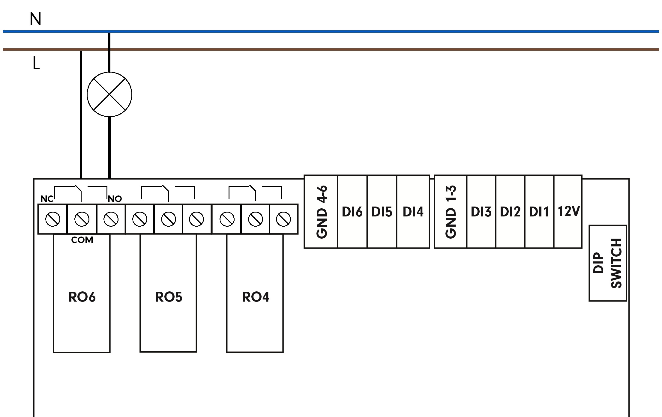
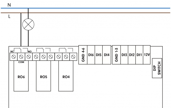
Connection
This illustration depicts connection of ohmic (resistance) load with alternating voltage to Unipi 1.1 Lite relay output:
Technical parameters
The data below represent a selection of the most important parameters and serve only as a quick reference.
Detailed information can be found in the product datasheet provided by the relay manufacturer:
Omron G5Q-14-EU
| Output type | Electromechanic non-shielded relay |
| Designation on the board | RELAYx (where x represents the relay number) |
| Number of terminals per relay | 3 |
| Terminal designation | Schematic (on the board) |
| Common terminal (COM) | Middle terminal |
| Closed without voltage (NC) | Terminal engaged according to scheme |
| Open without voltage (NO) | Terminal disengaged according to scheme |
| Contact/Output type | Switchable NO/NC (SPDT) |
| Number and type of relays | 6 × Omron G5Q-14-EU |
| Switching voltage | 250 V AC
24 V DC |
| Max. switching current for VAC | 10 A (NO)
3 A (NC) |
| Max. switching current for VDC | 5 A (NO)
3 A (NC) |
| Mechanical lifetime | 10 000 000 |
| Electrical lifetime | Up to 100 000 (according to the connected load) |
| Switching speed | 10 ms / 5 ms |
| Minimum time between closing and opening | 200 ms |
| Designed for load character | Resistive |
| Load handling | External (RC, varistor, diode, thermistor) |
| Short circuit protection | No |
| Overvoltage protection | No |
| Galvanic isolation | Yes |
| Insulation voltage | 4 000 V |