Analog inputs
Analog inputs on Unipi 1.1 serve for reading 0-10 V⎓ voltage or resistance sensors (eg. Pt1000 temperature sensors). For resistance measurements, it is necessary to perform an external adjustment. The negative pole of the measured external device is connected to the AIx- terminal of the given connector while the positive pole (signal) is connected to the AIx+ terminal (x represents the input's number).
Unipi 1.1
Analog inputs are available only on Unipi 1.1
Connection
The following pictures illustrate connection for measuring a voltage source on terminals AI2+, AI1-, AI2+ and AI2-.

Resistance measurement
If you need to use the Unipi 1.1 to measure resistance (eg. from Pt1000 temperature sensor), you need to add a resistor between the sensor and the board, as shown on the picture below:

12 V⎓ power supply on Unipi 1.1 is designed for digital inputs and can act as float voltage. For accurate readings we recommend using external power supply:
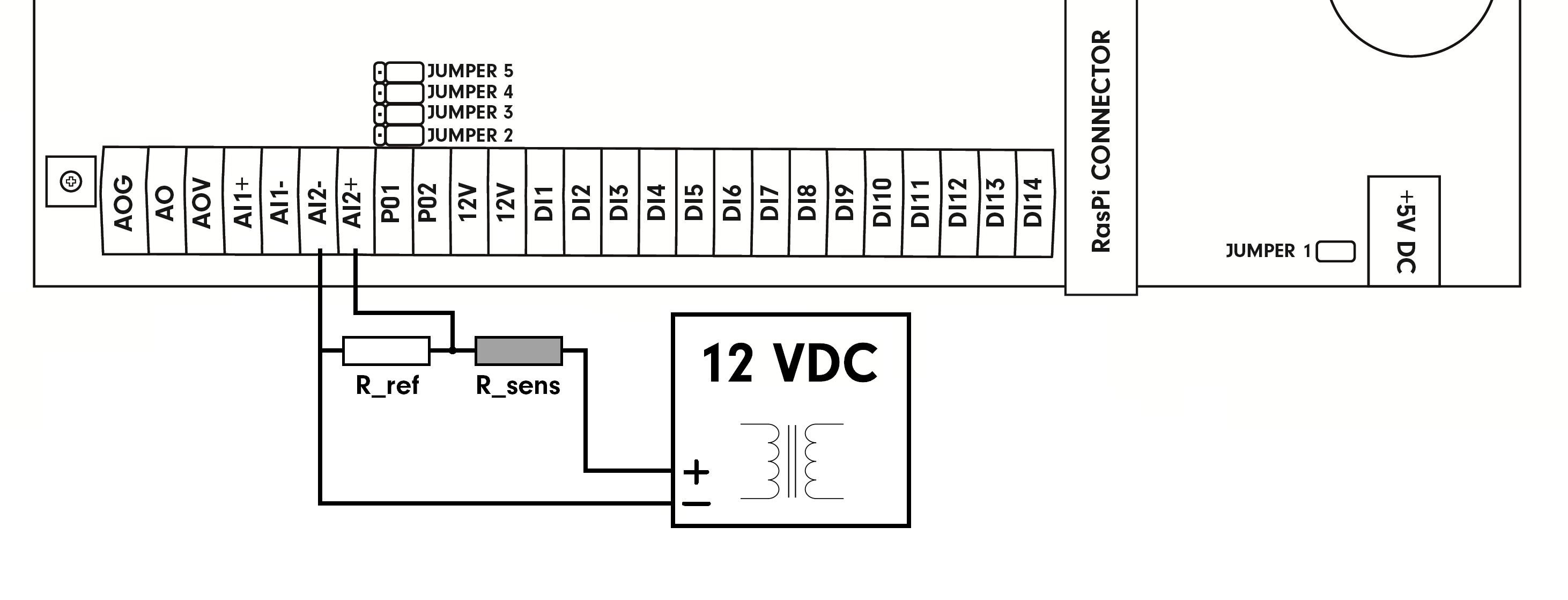
R_sens = sensor resistance (400 Ω - 5000 Ω)
R_ref = reference resistor (1.2 kΩ)
R_ai = AI input resistance = 12.2 kΩ
Vcc = voltage supplied to the circuit. The image above depicts 12 V⎓ voltage.
V_ai = measured voltage between AIx+ and AIX-.
At 12 V⎓ voltage and R_sens >= 200Ω, use reference resistance R_ref = 1.2 kΩ. At R_sens < 200 Ω use R_ref = 10 kΩ.
The R_sens value of the measured resistance is calculated using voltage measured on the selected analog input:
             Vcc - V_ai     R_ref * R_ai
   R_sens = ------------ * --------------
                V_ai        R_ref + R_ai
An example of calculating the read resistance: PDF download
Use of clamps
Use of clamps with the original WAGO tool.
Use clamps with a small flat-blade screwdriver.
Technical parameters
| Input terminals | AI1+, AI2 |
| Reference ground (GND) | AI1-, AI2- |
| Number of inputs | 1 |
| Input functions | 0-10 V DC voltage measuring (can be used to resistance measurements if set as a voltage) |
| Maximum input voltage | 12 V DC |
| Measuring accuracy | ±0.5 % |
| Resolution | 32 bits |
| Galvanic isolation | No |