This is an old revision of the document!
First project with a Unipi controller
Every initial startup guide includes blinking LEDs or switching relays, and this tutorial is not an exception. Using this guide, we will create the simplest project possible with the intent to switch digital output in 5s interval.
Patron
Neuron
Gate
Axon
The following tutorial includes all basic configurations needed to create the core of a Mervis IDE project and to deploy it to Patron, Neuron, Gate, or Axon controller. All following tutorials use this one as their cornerstone. The last chapter of this manual is a well-known flashing diode, ie a program in FUPLA blocks switching the digital output and its indication by a diode.
Prerequisites:
- a computer with Mervis IDE installed

For this tutorial it is NECESSARY to:
- Only for Patron PLCs: upload Mervis OS into an Patron controller
- Only for Neuron PLCs: deploy Mervis OS to an SD card
- Only for Gate PLCs: upload Mervis OS into an Unipi Gate device
- Only for Axon PLCs: upload Mervis OS into an Axon controller
- plug in the power supply (wait at least for a minute before the PLC's OS boots up
Creating a project
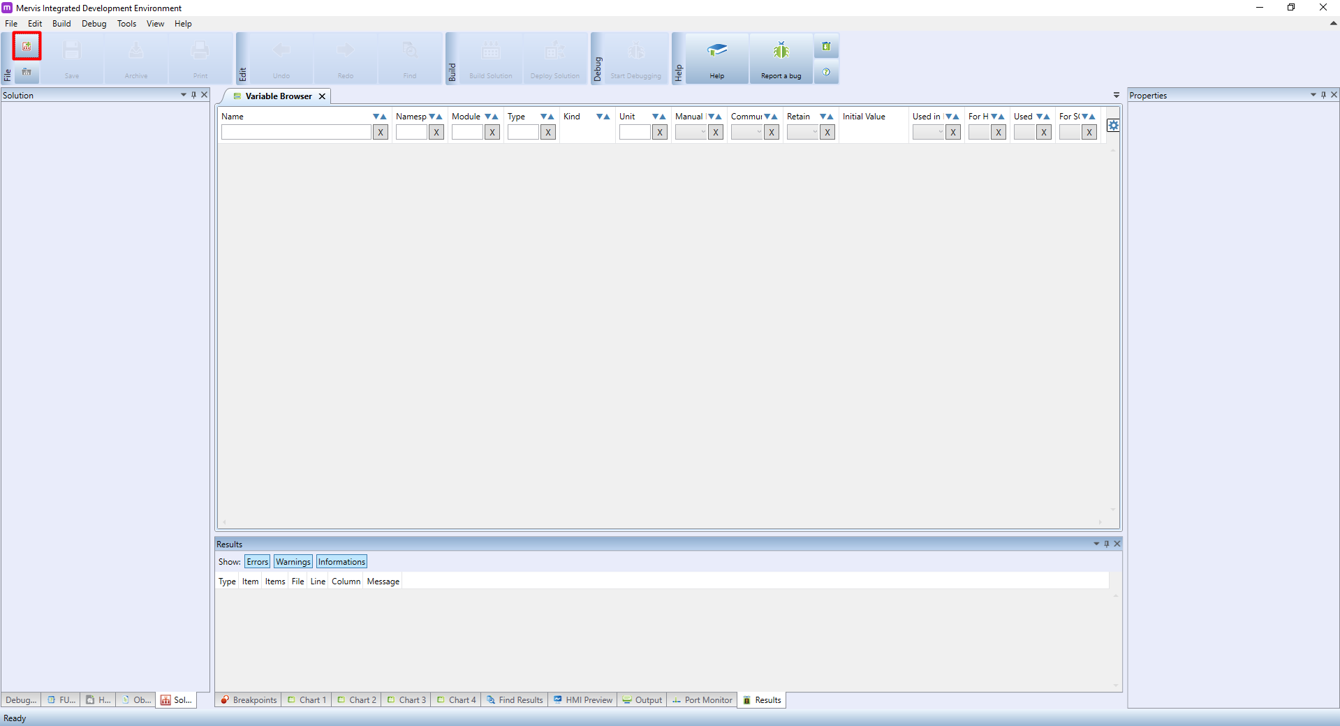
In Mervis, a single project (eg. a set of configurations, programs and HMI interfaces) is known as a Solution. To create a new solution click on File → New solution (Ctrl+N), or click on the  icon on the upper ribbon.
In the New solution dialogue window you need to enter the solution's name and the location it will be saved into. Fill both fields as required and confirm by clicking on OK.

The second thing you need to specify when creating a solution is Mode selection. The mode determines the behaviour of the Mervis IDE during its use; Simple Mode pre-defines the whole core of the solution, i.e. defines basic programs, generates mapping of variables, etc. At the same time, however, this option will limit the selection of the programming method only to Function Block Diagram (FBD). Simple mode is therefore especially suitable for beginners. For more experienced users, there is a Full mode from which you can switch to the Simple mode, but this step is irreversible. Full Mode does not create the initial project structure and the entire basic configuration is up to you.
That said, it might be convenient (with the exception of some special cases) to create the solution's core automatically in a Simple Mode and only then to switch to Full Mode.

Attaching to the controller
Securing the controller
Securing the PLC users:
WARNING: If the login info remains at default values, it may result in unauthorized personnel gaining access to the controller. This may cause unauthorized modifications of the system, leading to stoppage or limitation of the controlled technology. In the worst-case unauthorized access can cause damage to the technology, or even endanger maintenance personnel at the installation site.

- Create and remember your unique passwords and logins
- Find user definition section in the PLC properties
- Enter your login info
- It is important to not only change all passwords, but also their logins
- Leave the PLC connection parameters unchanged
- Now upload the configuration into the controller - follow this guide.
- After uploading the configuration, look for the PLC Connection Parameters, change the login (Engineering) entered in the previous step and save the solution
- If you leave PLC Connection Parameters unchanged, Mervis IDE will be unable to connect to the PLC
- Your PLC is now secured against unauthorized access
“Engineering” user has full access to all PLC configurations including changes in the control program, HW settings etc.
“Full control” user has access only to the control program variables and can read from them or write into them. However, this user cannot change configurations or the control program itself.
“Read-only” user is able only to read from the control program variables.

 Secured connection with the PLC:
Secure connection has been introduced in the Mervis IDE v2.3.0.
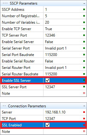
- Look for SSCP Parameters in the PLC properties (network settings section)
- Set Enable SSL Server to
TRUE - upload the configuration into the controller. Follow this guide.
- With the configuration uploaded, look for Connection Parameters, change the TCP port to
12347and set Enable SSL toTRUE - Any connection between Mervis IDE and your PLC will be now secured.
Connecting the inputs/outputs
This step is done automatically since Mervis IDE 2.2.0 for Patron, Neuron and Axon controllers and adds only the default Modbus TCP channel. Additional channels (1Wire, Modbus RTU) has do be done manually.
Now that we attached to the running controller, we can configure the inputs and outputs. The Unipi is internally consisting of the CPU unit (running Mervis OS), and input/output backplane, which communicates with the CPU unit via ModbusTCP.
To connect to the backplane, we need to add Channel. The Channel is a communication point with hardware which happens in the defined protocol. To add Channel, right-click on the PLC name and then click on the Add Channel.
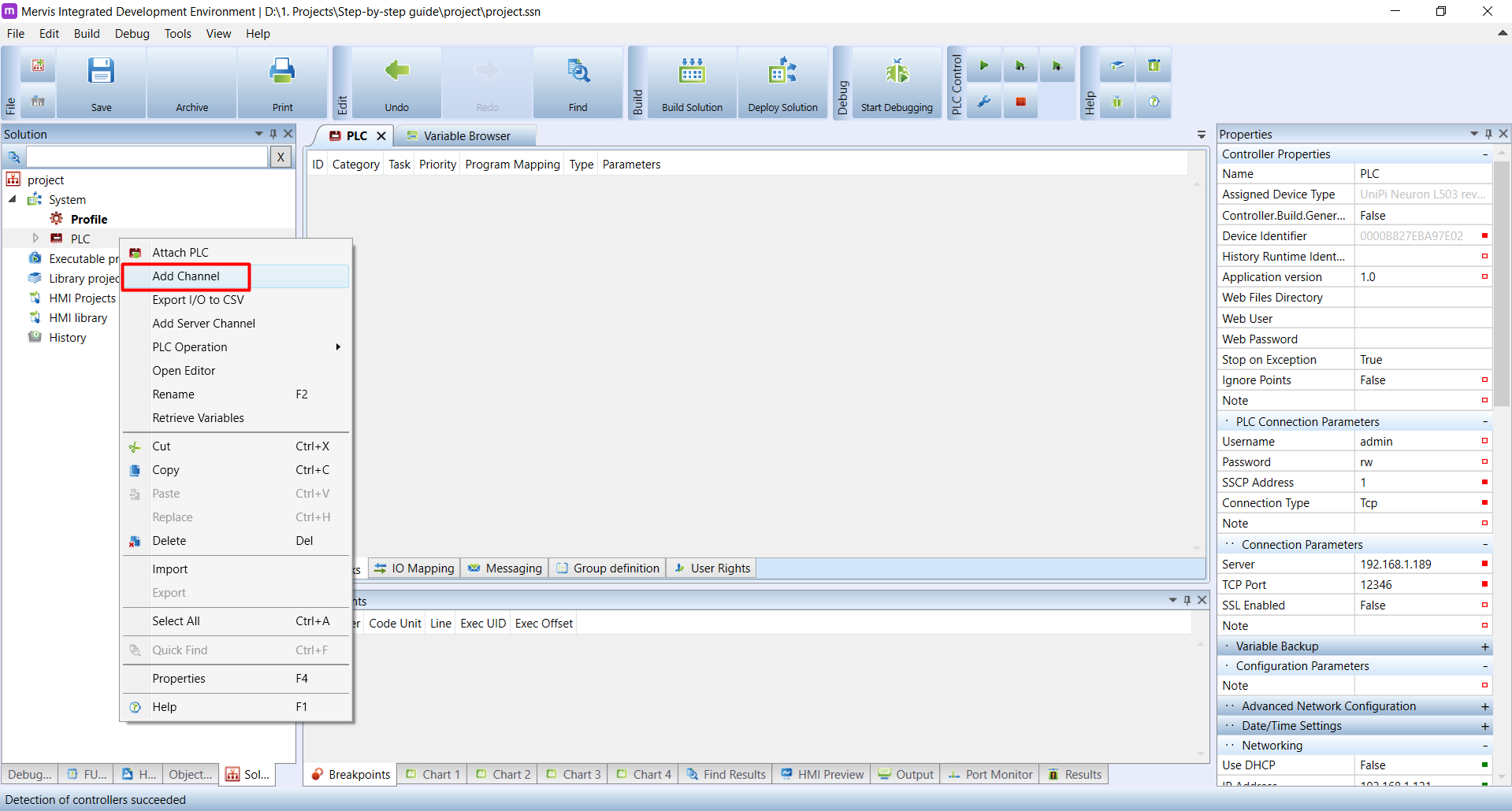
New communication channel will appear under the PLC. Click on it. In the Properties panel, you will see information about the channel. It is a good thing to rename the channel to something more descriptive, e.g. “ModbusTCP” since this channel is for ModbusTCP communication.

Next thing we need to change is the protocol to Modbus
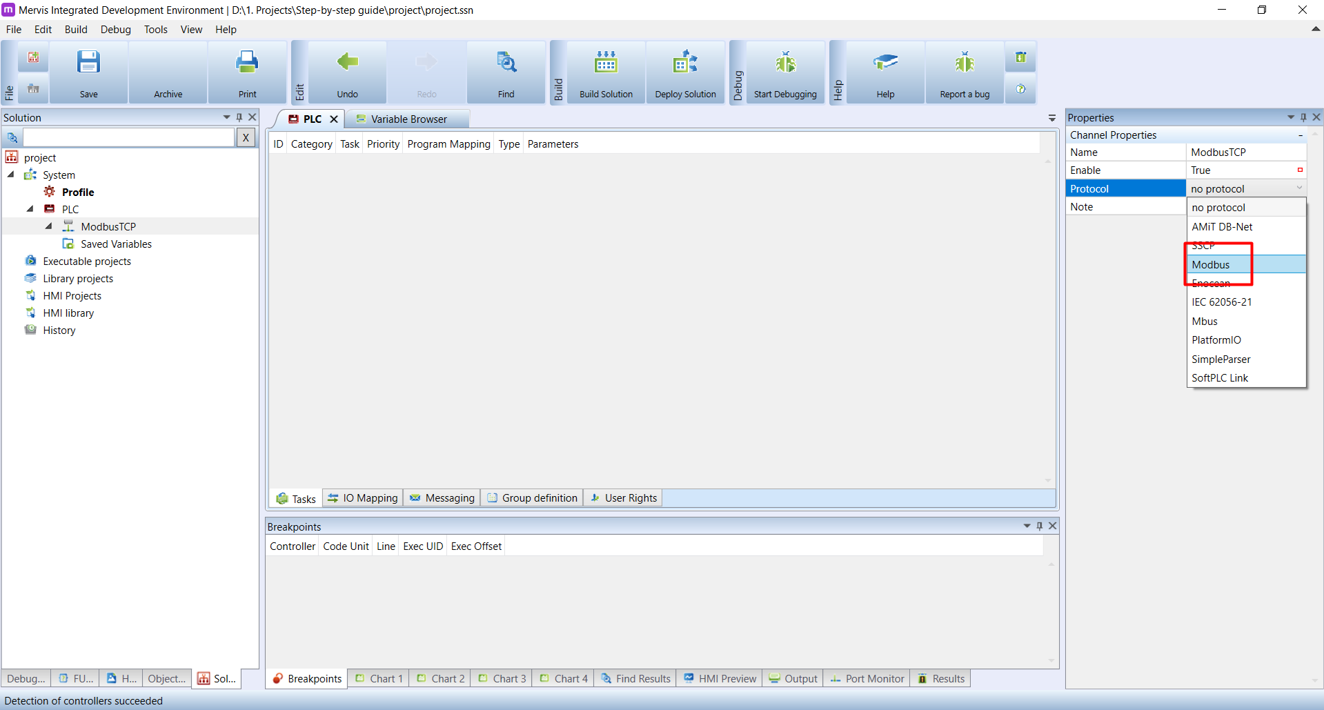
With Modbus protocol, we need to select correct Link Protocol. The default is Serial, but as we stated above, the UniPi backplane is connected via TCP.

The Channel is configured, now we can add the device. Right-click on the new channel name in the Left panel. It is under the PLC option tree. In the context menu, select the Add Library Device.
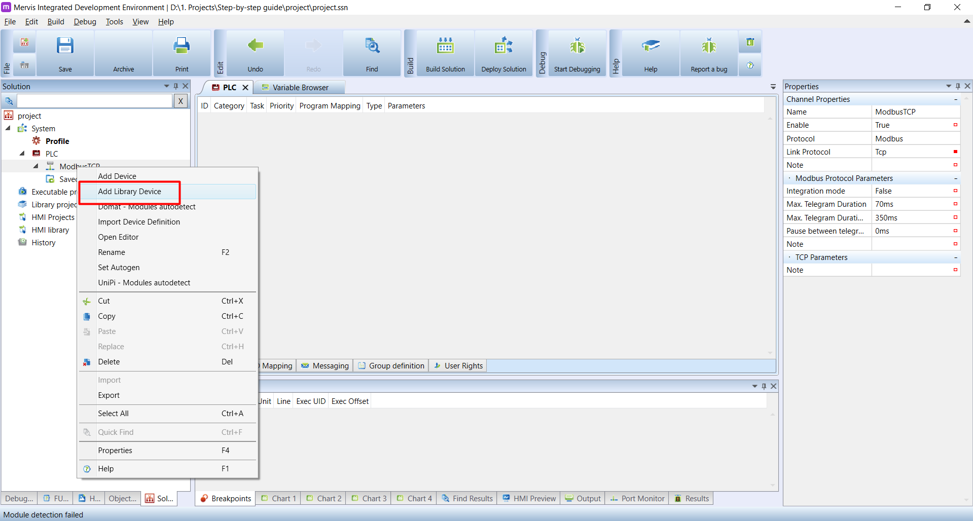
In the dialogue Add Library Device, there is a large list of the supported devices. For quick searching, type the model name of your controller into Device Name. In this tutorial, we use UniPi Neuron L503, and by typing L503, the unit was found. Select it by left click, and click on the ![]() icon to add it into the list of selected devices and then hit OK.
icon to add it into the list of selected devices and then hit OK.

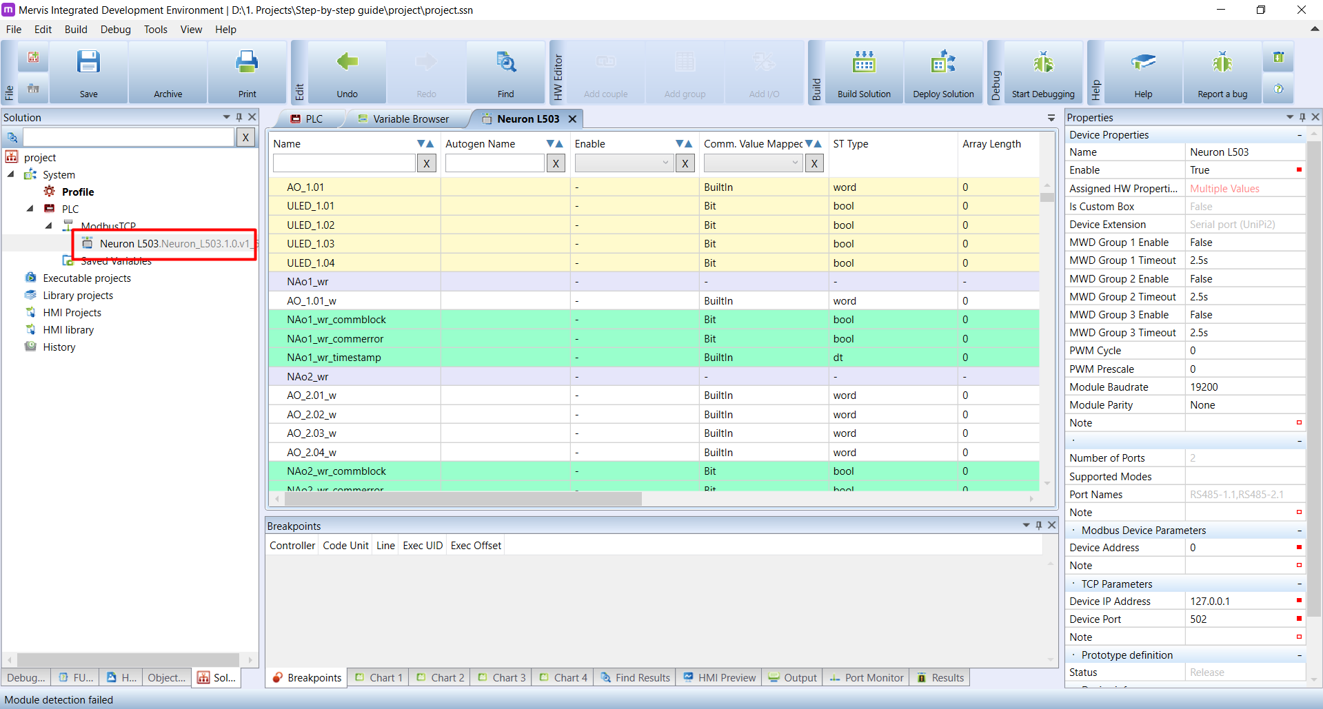
The new device appears under the ModbusTCP channel we created a few moments ago. Double click on the name and new tab will appear in the Main window containing the list of all inputs and outputs provided by the unit.
Uploading a blank configuration
Now it's time to talk about the configuration of modules. This applies greatly if you are starting to work with PLC or Extension, which has been previously used. The units can have stored configuration, which is independent on the uploaded solution and therefor the PLC can act differently than expected. But no need to worry, all you need to do is to apply blank configuration by following this tutorial. That's all you need to do right now and we will get back to this later in more details.
Creating a program
Next step in creating a working solution is to create a program.
In the Left panel, right-click on the Executable projects and in the context menu, click on the Add New Project.
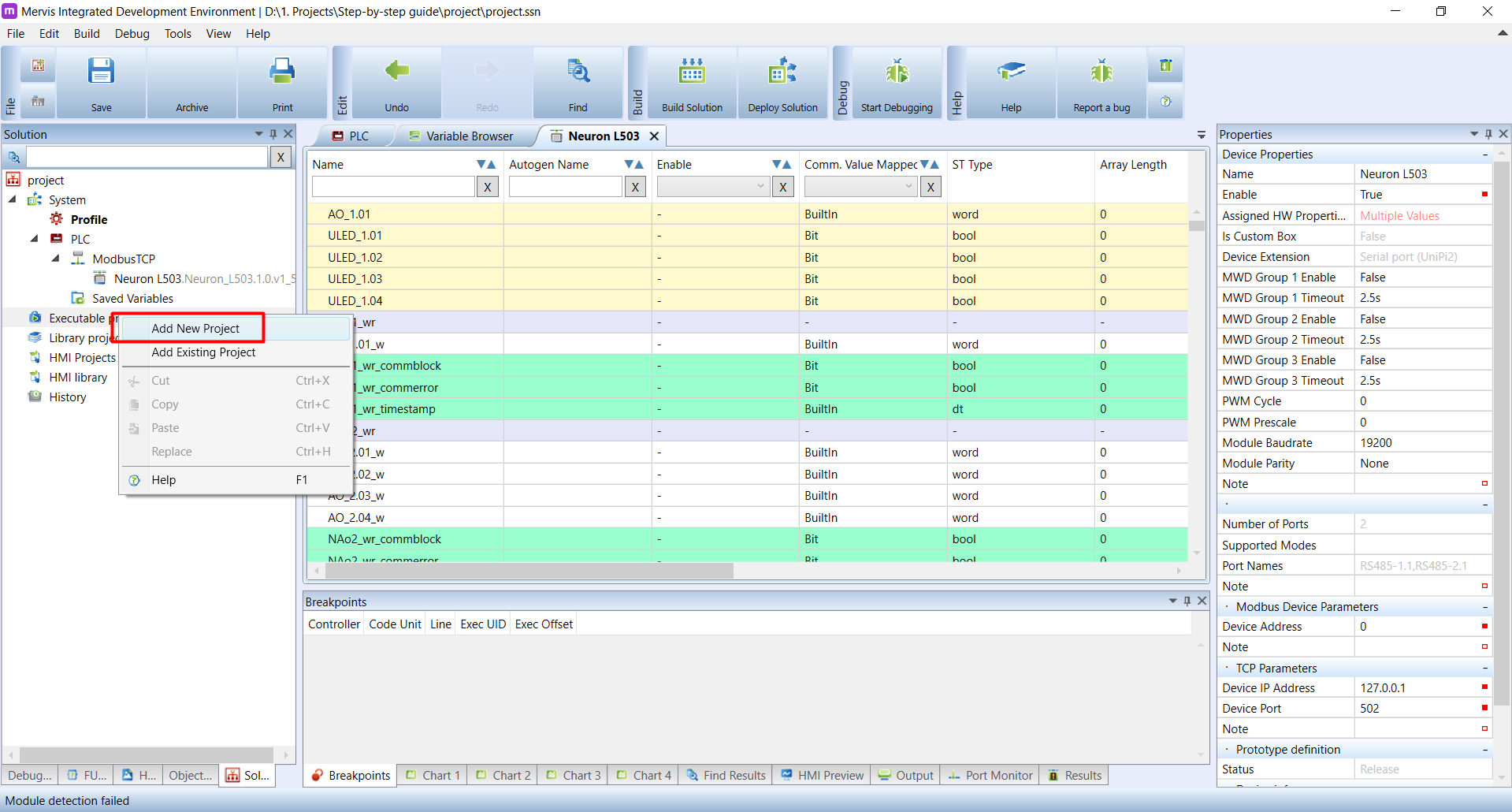
In the New Project dialogue, you have to fill the Name. The Location is automatically a subdirectory in the Solution directory, so you can leave it as it is and confirm by clicking on OK

In the newly created Executable project, you can create programs. Right-click on the name of the executable project, in our instance the mainProgram. In the context menu hover over the Add and in the submenu click on Add program.
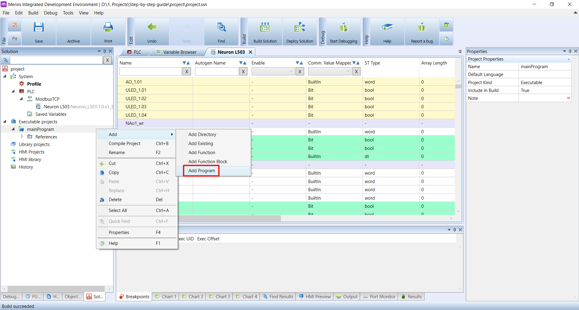
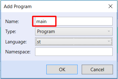
The dialogue Add Program will appear, and we have to set the Name. Let's call this program main.
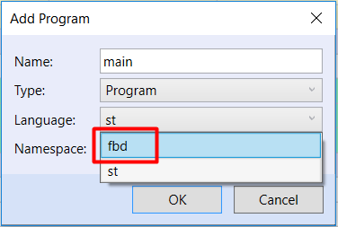
In the same dialogue, look at the Language option. By default, in the Full mode, the language is st which stands for Structured text. This is one of the 5 languages defined by the IEC 61131-3 standard, and one of 2 supported by the Mervis IDE. Since learning ST language is out of the scope of this tutorial, select the fbd, which stands for Functional block diagram and confirm the program creation by clicking on OK.
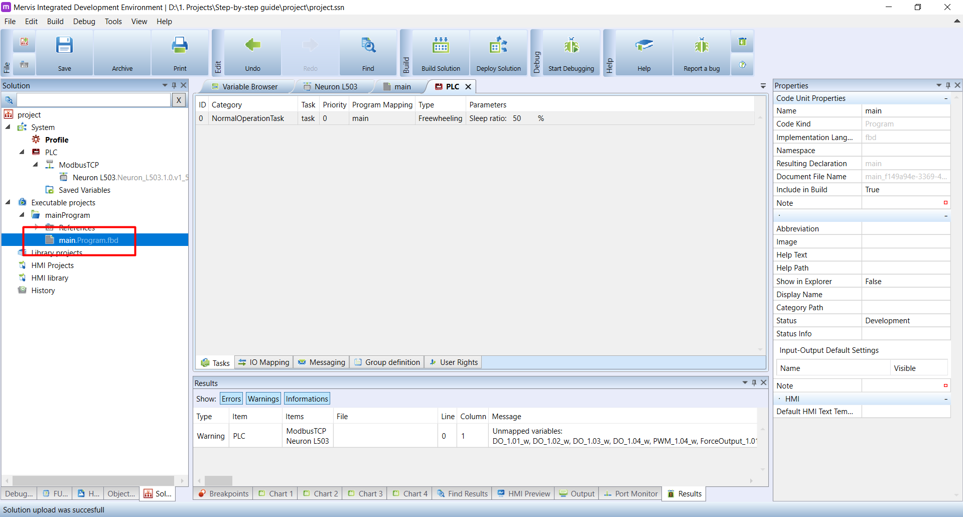
Under the mainProgram executable project in the Left panel appeared a new program named main.Program.fbd. Simultaneously the program has been opened as a new tab in the Main window. This is how your workspace should look like now:

You can close the program in the Main window and you can open it again, by double-clicking on the program name in the Left panel.
Setting a task
So far we have attached the controller, configure the access to inputs and outputs and created a structure of an executable project. We also created a main program, so far without any logic. The last thing to do in this minimalistic Solution is to tell the controller, which program has to be executed after the start. This is called Task.
The first step in adding a task is Build Solution to attach the main program to the project. Double-click on PLC in the left panel. In the main window a new tab will appear named PLC (or your name if you renamed the controller).

The PLC tab is divided into several panels between which you can switch using tabs on the main panel's bottom edge. Visible are tabs Tasks, IO Mapping, Messagingm Group Definition a User Definition. As you can see, we have no task created at the moment.
Let's start adding the task by double-clicking on the PLC name in the Left panel. In the Main window, a new tab called PLC (or the name of the PLC, if you renamed it in its properties) will appear.
The PLC tab is divided into subpanels. You can switch the subpanels at the bottom of the Main window. You can see the tabs Tasks, IO Mapping, Messaging, Group Definition and User Rights. We are interested in the Tasks tab, which should be active. The Main window of PLC tab therefor shows a list of defined tasks for this controller. As you can see, there are no tasks.
To add a new Task, right-click on the space in the Main window and in the context menu, select Add Task.

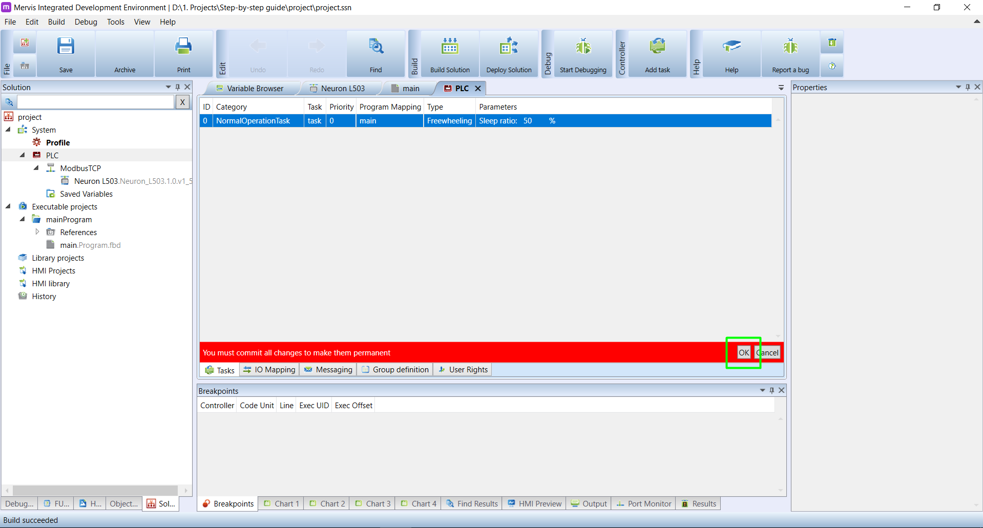
New Task will appear in the list. You can see, that there is no value in the Program Mapping. To map a program to this task, click on the blank space.

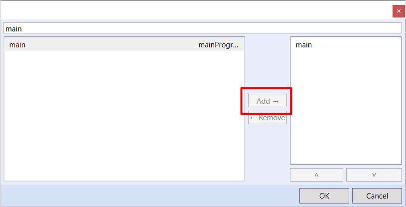
A new dialogue will appear where we can see a list of our programs. So far, you should see only main program. Select it by clicking on it and then click on the ![]() to add it into the right list. And confirm by clicking on OK.
to add it into the right list. And confirm by clicking on OK.
Now we are back in the list of tasks. You can see a red warning at the bottom about committing changes. Click on the OK to commit the changes.
Now we finished the bare minimum to deploy this Solution to the controller.
Building a solution
Building a solution means taking all the executable and HMI projects, library projects and HMI libraries and creating a binary for runtime environment in Mervis OS. The build will check if everything is ok and warn you if something prevents successful build.
To build the project, click on the Build button on the Ribbon
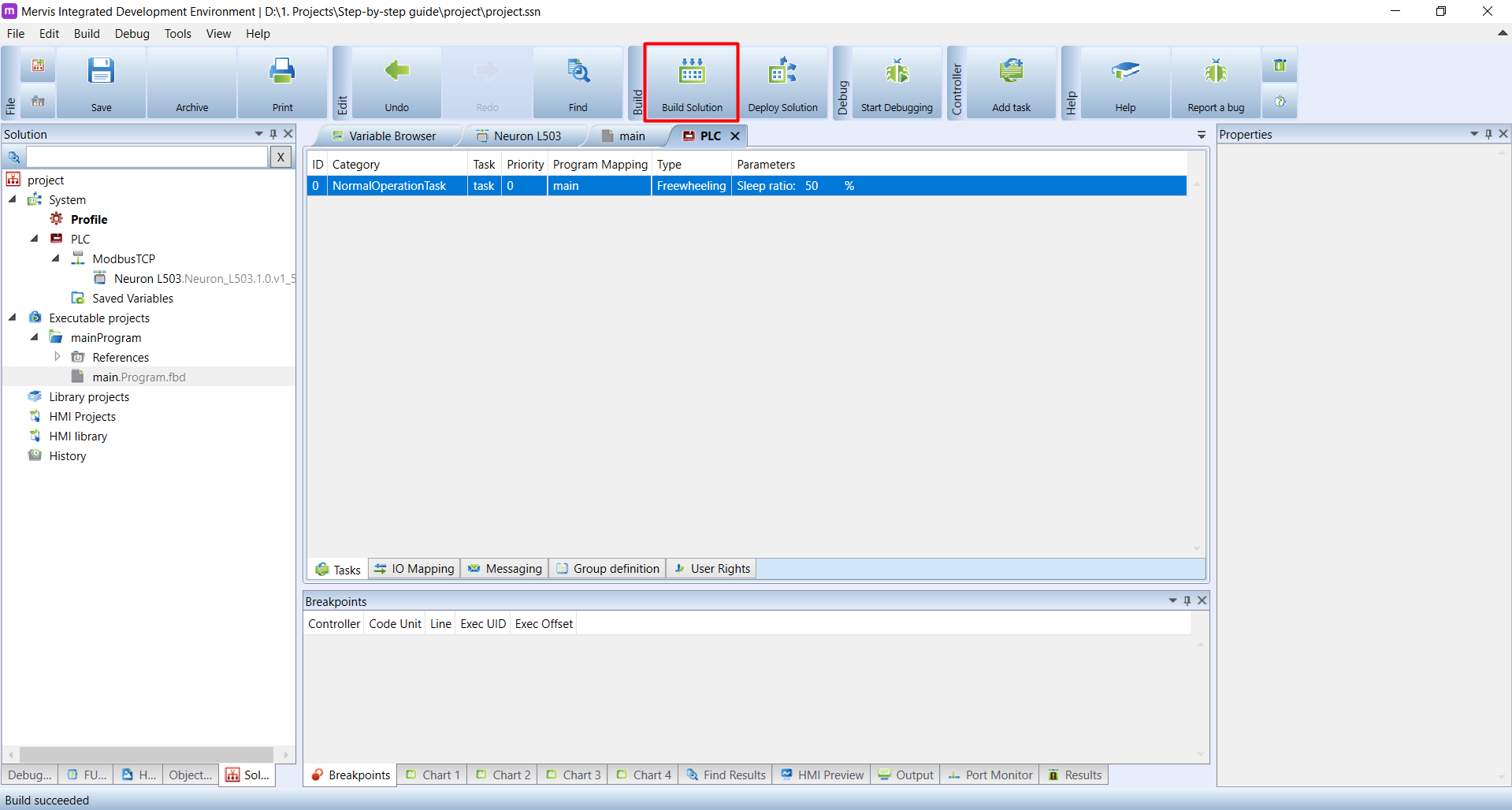
A dialogue Selected devices to build appears and shows you the list of attached PLCs, for which you want to build the project. By default, all attached PLCs are selected. Confirm the selection by clicking on the OK.
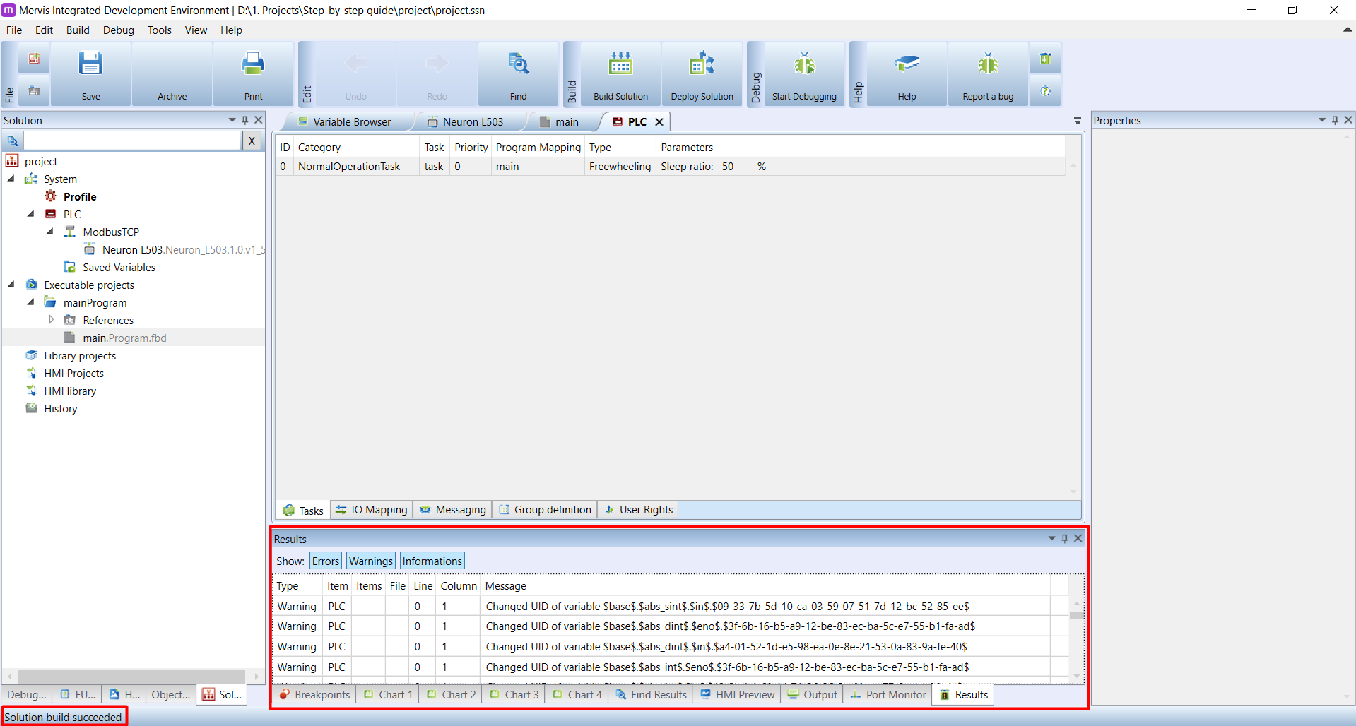
The build will start and in the Bottom panel on Result tab you will see messages. On the Status bar you will see the overall result of the build. If you followed this tutorial precisely, your build should pass with Status bar message “Solution build succeeded”.
Deploying solution
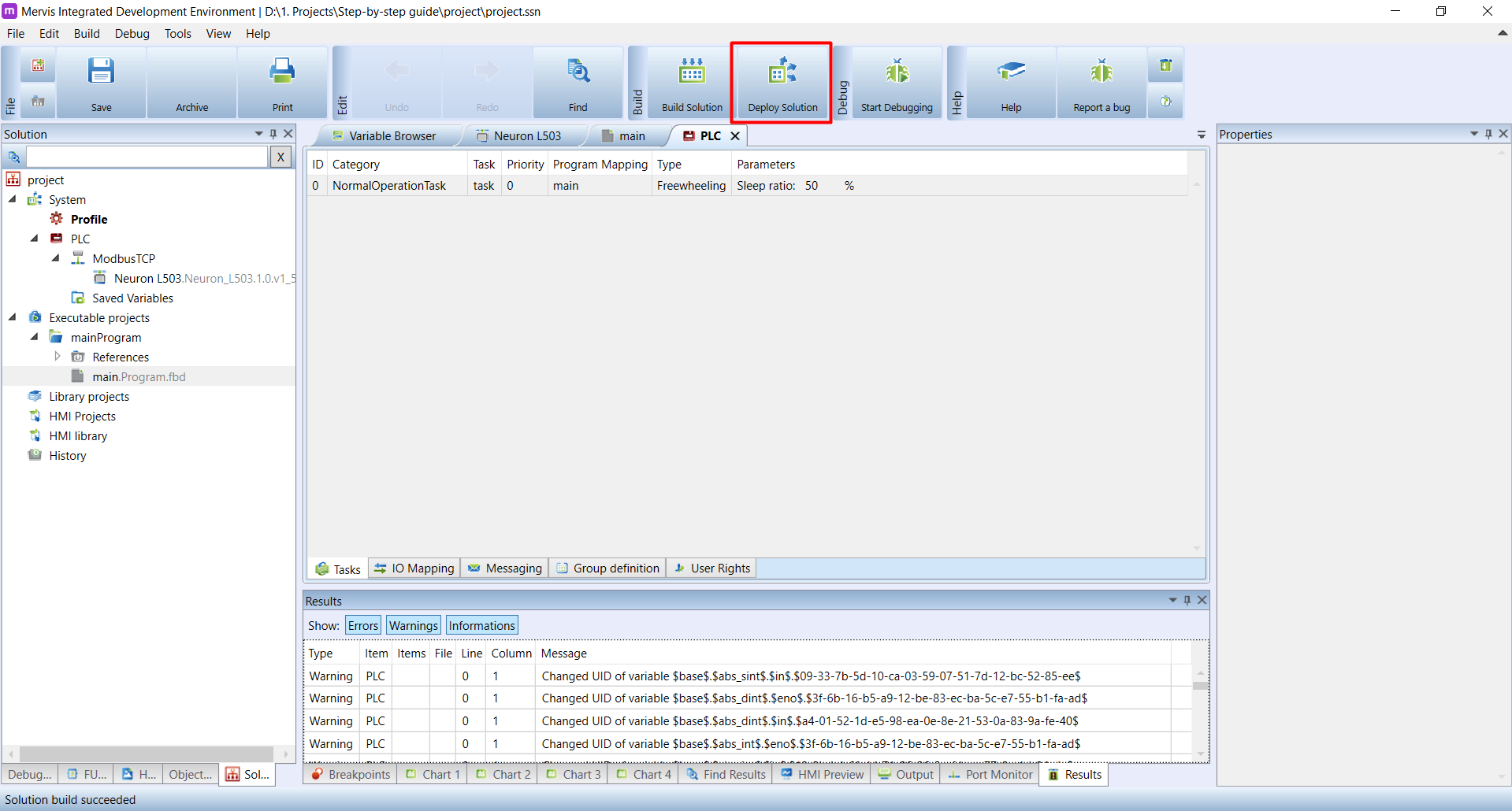
Deploying solution means downloading the previously built binary to the controller and selecting the PLC's Run mode. To deploy a solution, click on the Deploy button on the Ribbon
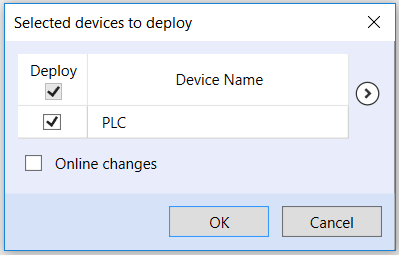
As with the Build you will be asked into which PLCs you want to deploy the solution. Confirm the selection by clicking on OK
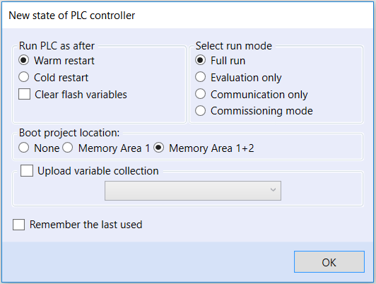
The last thing of the deploy is to set the new state of the Unipi controller. There are several options, but right now, leave the selected options Warm restart, Full run and Memory Area 1+2. For now, confirm by clicking on OK.
Blinking LED
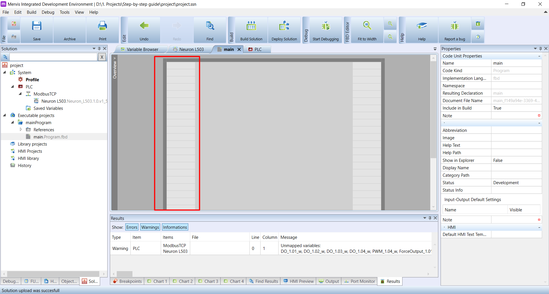
Let's create our first program, which will blink with the status LED of the DO1.1 output. The blinking means we will periodically set the DO1.1 output to true and false. We have the basic Executable structure finished, so we can fill the main program with some logic. Double click on the main.Program.fbd option on the Left panel.
The program window will appear on the Main window. The program canvas is divided into three sections. On the left, we have Input area. Each grey box can be filled with some input variable.
On the centre is the Logic area, where all the magic of our program is happening.

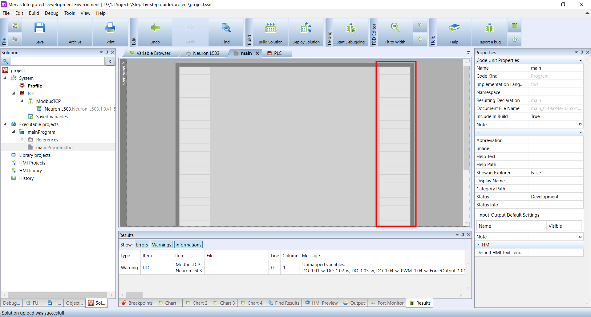
And on the right side is the Output area. Each grey box can be filled with some output variables.
Now we could dive into the FBD programming for a long time, but we want to see some results first. So on the bottom of the Left panel, click on the FUPLA Box Explorer. The FUPLA Box Explorer is placed, where you can find Function blocks (FBs), which are the cornerstone of the FBD programming. Each FB does a certain thing. It has some internal logic, some inputs, which alters the behaviour of internal logic and some outputs of the logic which can be wired to other FBs or some HW outputs.
Right at the top of the Left panel, you can see a search box, which allows you to lookup FBs predefined in Mervis.
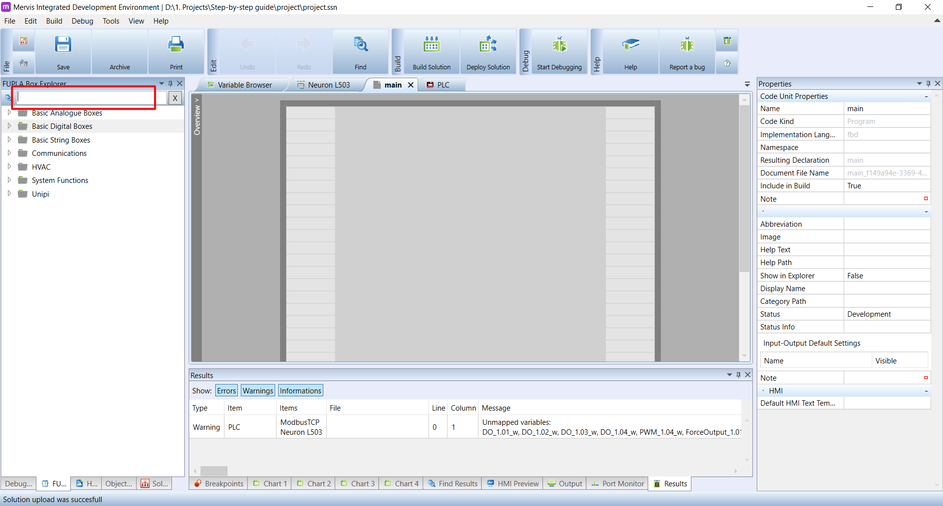
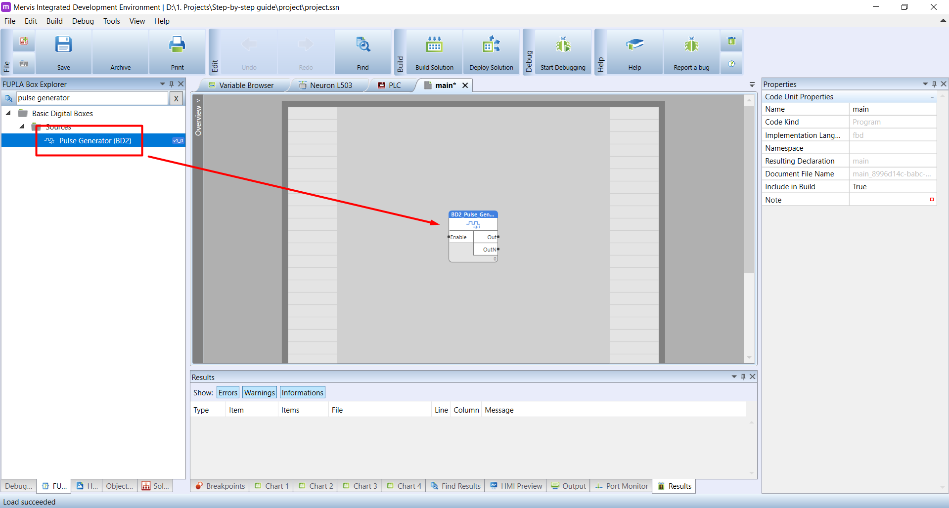
Let's search for the pulse generator. Enter the pulse generator into the search box. As you type, you can see that the search results below are refining and after finishing your search you will see only one result. Grab the FB Pulse generator (BD2) (left click and hold), move it above the Logic area and release the mouse button.
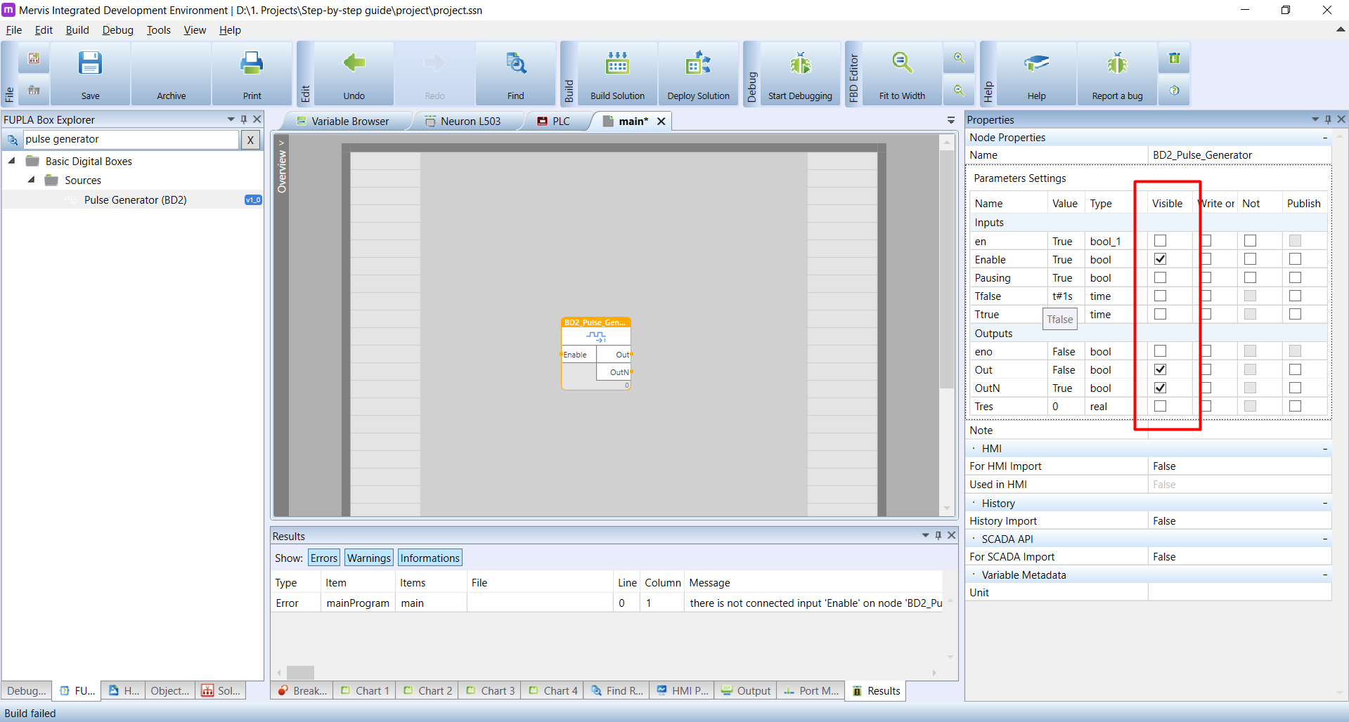
The BD2 Pulse Generator functional block has a simple logic. It periodically sets output Out to true and false with the frequency of 1Hz. Ideal for our blinking example. Let's investigate the FB's inputs. On the FB itself, you can see input Enable and outputs Out and OutN. Click on the FB - it will turn yellow which is the indication, that the FB is selected. Now you can see it's properties on Properties panel. In the section Parameters settings, you can see a list of inputs and outputs. As you can see, there are much more inputs and outputs, than it is available on the graphical FB. It is because most of them are hidden. The visibility of the input or output is configurable via it's Visible property. Because we don't need anything else from the Pulse generator other than Out output, uncheck the Visible property on the rest of them. Also, Mervis IDE doesn't allow unconnected inputs/outputs and such FB will fail the Build.
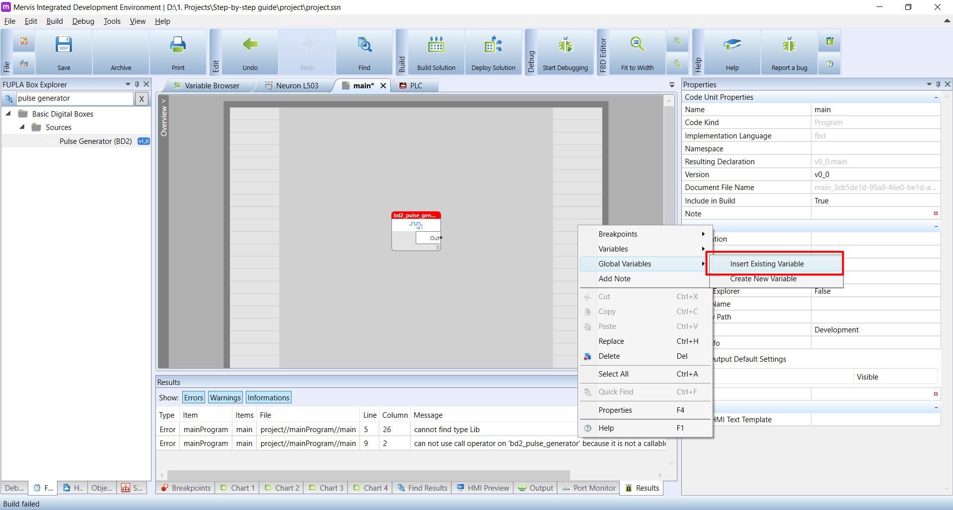
Now we have to wire the output of the pulse generator to the DO1.1 output. Right-click on the Output area of the program. In the context menu hover over the Global Variables and from the submenu select the Insert Existing Variable
In the Insert Existing Variable dialogue, you should see a list of all variables and inputs and outputs of your controller. But wait! There is almost nothing. What happened?
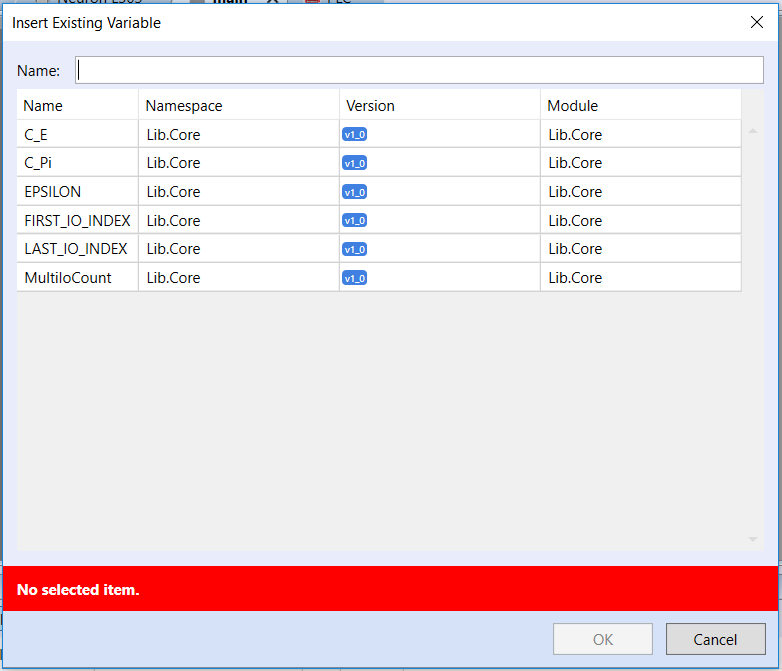
The missing variables in the program are a common problem. The devices we defined under the PLC's channels have some defined inputs and outputs. You can see them in their definition. But to have them available in the program as well, you need to generate their list into the Executable project you are working with. This can be done by the Set Autogen functionality
We very briefly mentioned the Autogen in the Creating project section - that the Autogen is automatically set in Simple mode and you have to run it on manually in Full mode.
The Autogen does a one-time generation of program variables from the list of inputs/outputs. That means, even when we added a device, we have to generate the list of variables to be able to use it in the program. To generate the list, switch to the Solution tab on the Left panel. Right-click on the device name from which you want to generate the variables and then click on Set Autogen.
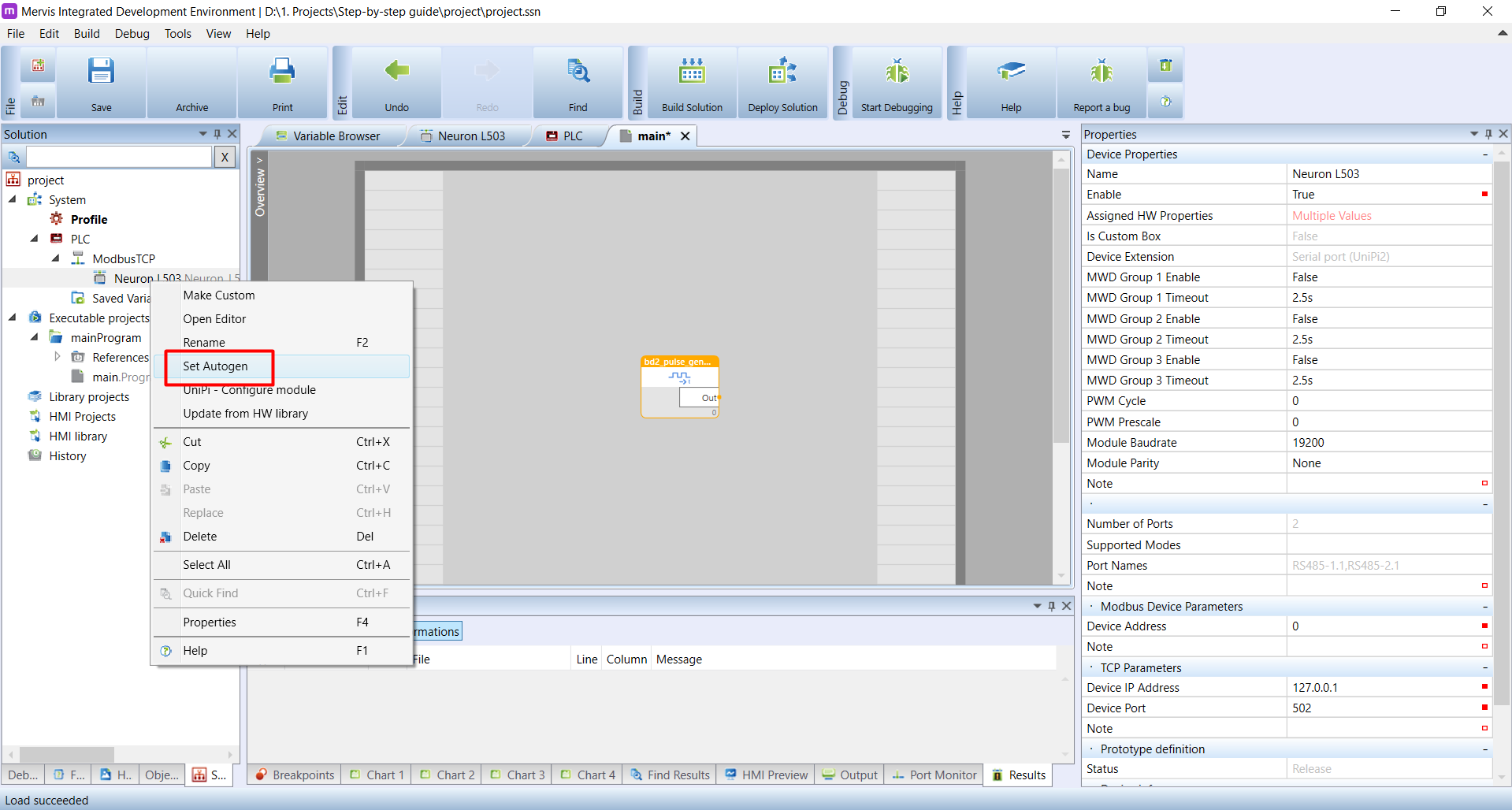
On the Set Autogen dialogue, you have everything prepared for confirmation by clicking on OK.

The last thing you need to remember with Set Autogen is, that it is one-time generation. If you, for example, rename some input/output on the device, you need to run it again
Now we have the variables available in the program and we can add our DO1.1 output to the pulse generator. Right-click on the Output area of main program, hover over the Global Variables and from submenu select the Insert Existing Variable.

In the Insert Existing Variable, you can see a large list of possible variables. You can look for the variable manually, or you can search by the part of its name. We will search for do, which stands for Digital output. On our Unipi Neuron L503 unit, we have digital outputs DO1.1, DO1.2, DO1.3 and DO1.4. In the list, you can see all four twice, with _r and _w name suffix. Since we want to write to the digital output, we will select the Neuron_L503_DO_1.01_w variable and confirm the dialogue by clicking on OK.

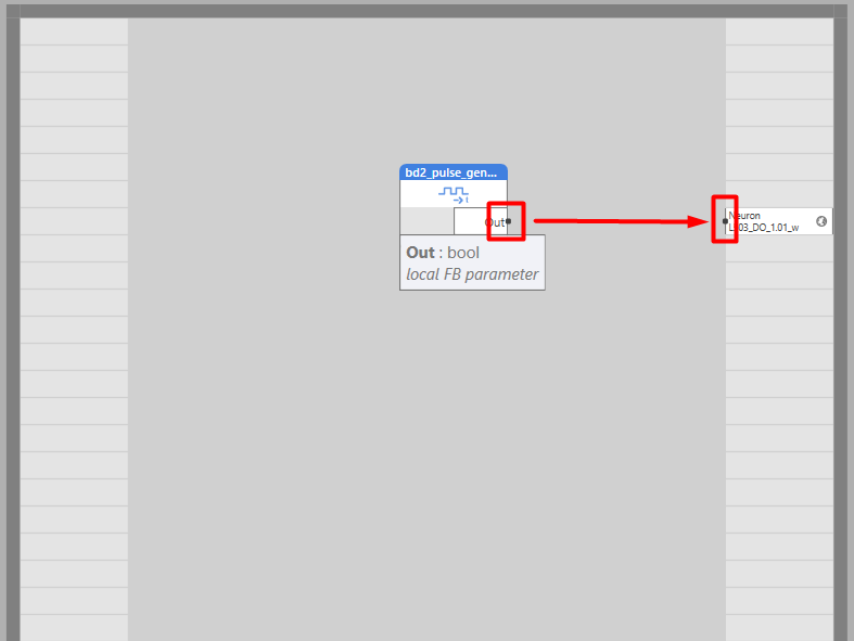
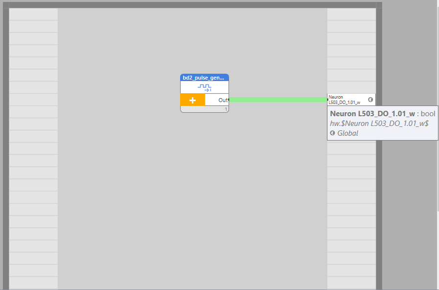
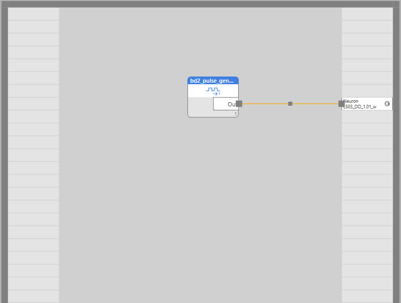
The output variable will appear on the Output area where we right-clicked. Now we need to wire the output of the pulse generator FB to our output. Move the mouse cursor over the black dot right next to the Out output name of the pulse generator. A small box will appear containing information about the output type. Click on the black dot, hold the button and wireline over the black dot right next to the name of the output variable until the newly created line goes green and then release the button. You can see all three steps on the next screenshots.
Now you can try to Build the solution by clicking on the Build button in the Ribbon. If everything goes well, you should see a Build succeeded in the Status bar. Don't mind the warnings in the Results tab in the Bottom window.
And if the build succeeded (it will, if you follow the tutorial precisely), you can Deploy it to the controller. See the Deploying solution section.`
Once the solution is deployed, the DO1.1 status LED will blink in the 1s interval. Congratulations! You just finished your first project with Unipi.
Switching from Simple mode to Full mode
The last thing to mention is how to switch the Solution from Simple mode to Full mode. Right-click on the Project name option (first option) in the Solution tab on the Left panel. In the context menu, click on the Switch to Full mode.
Congratulations, your first project with Unipi PLC is now complete!