First project with Unipi 1.1/Lite
Every initial startup guide includes blinking LEDs or switching relays, and this tutorial is not an exception. Using this guide, we will create the simplest project possible with the intent to switch relay in 5s interval.
Unipi 1.1
The following tutorial includes all basic configurations needed to create the core of a Mervis IDE project and to deploy it to Unipi 1.1/1.1 Lite controller. All following tutorials use this one as their cornerstone, with the relay switching being the last chapter, using a FUPLA block program.
Prerequisites
- MicroSD card for the PLC
- MicroSD→SD adapter or a microSD card reader with USB connector
- Downloaded archive with Mervis OS for Unipi 1.1/Lite
- Computer with Mervis IDE installed.

For this guide it is NECESSARY to:
- Plug in the power supply and wait for at least a minute until the PLC's OS boots up.
Creating a project
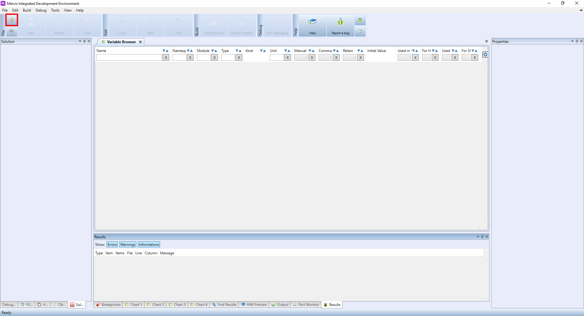
In Mervis, a single project (eg. a set of configurations, programs and HMI interfaces) is known as a Solution. To create a new solution click on File → New solution (Ctrl+N), or click on the  icon on the upper ribbon.
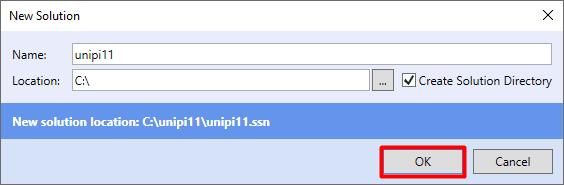
In the New solution dialogue window you need to enter the solution's name and the location it will be saved into. Fill both fields as required and confirm by clicking on OK.
The second thing you need to specify when creating a solution is Mode selection. The mode determines the behaviour of the Mervis IDE during its use; Simple Mode pre-defines the whole core of the solution, i.e. defines basic programs, generates mapping of variables, etc. At the same time, however, this option will limit the selection of the programming method only to Function Block Diagram (FBD). Simple mode is therefore especially suitable for beginners. For more experienced users, there is a Full mode from which you can switch to the Simple mode, but this step is irreversible. Full Mode does not create the initial project structure and the entire basic configuration is up to you.
That said, it might be convenient (with the exception of some special cases) to create the solution's core automatically in a Simple Mode and only then to switch to Full Mode.

Attaching the controller
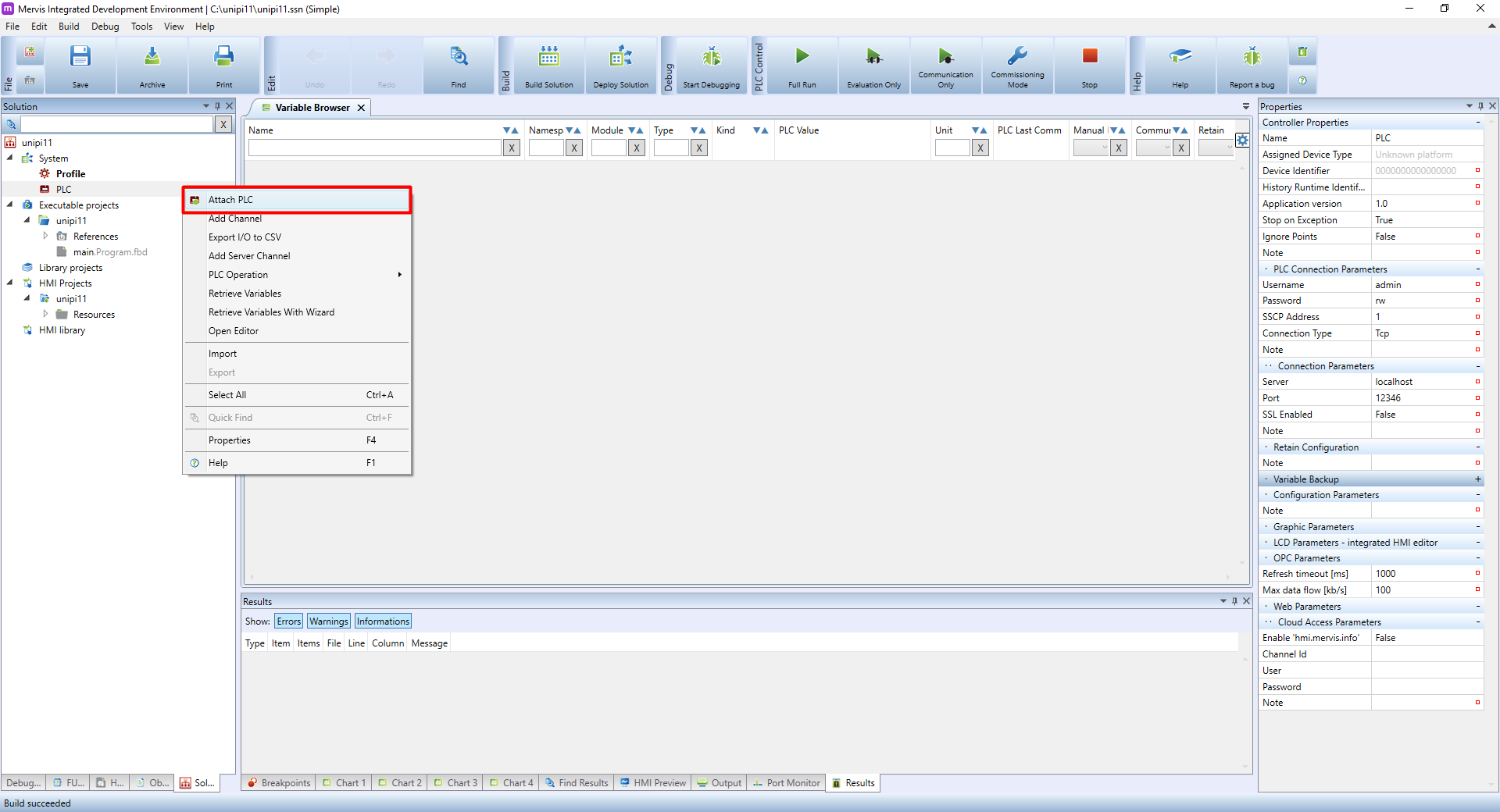
Next step in creating a Solution is to connect to the running Unipi controller. In the Left panel on Solution tab, right click on the PLC and then click on the Attach PLC.
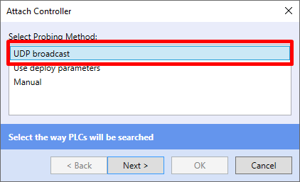
The Attach Controller dialogue will appear, in which we can specify, how the Mervis IDE should connect to the controller. If the PLC is in the same LAN network, you can use the UDP Broadcast and then click on Next >.
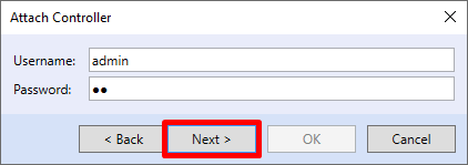
You will now be prompted to enter a username and password (SSCP access) to connect to the controller. The default setting is: admin / rw. Now leave and click Next >.
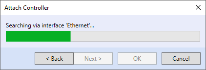
Next window will show a progress bar as the Mervis IDE is looking for controllers on all network cards your computer has.
After the searching is finished, you will be presented with the list of all detected controllers. The target controller has its name displayed in the Platform tab. This tutorial used Unipi 1.1 device - in your case, choose whatever controller you are using and click on Next >.
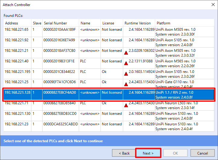
In some cases, you will see a red triangle next to the Runtime version. This means the runtime is older than the IDE expects. To fix this problem, follow the Updating runtime (RT) tutorial.
If you see a small skull next to the Runtime version, the controller's operating system is outdated and you need to upload a current version of Mervis OS. The guide for uploading Mervis OS for Unipi 1.1/Lite.
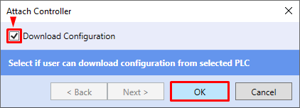
The last dialogue of the controller attaching process asks you about configuration download. The configuration holds basic settings of the Unipi controller, such as IP address, usernames and passwords, connections to Mervis DB and Mervis Proxy and so on.
When assigning a new controller for the first time, we recommend that you always download the configuration.
The controller has now connected.
Select the item PLC in the left panel, after selecting it the properties of the connected controller will be displayed in the right panel Properties. This property panel is crucial, since you are setting up the controller configuration there. The properties include, for example, network configuration, security, database connection, SSCP, proxy, etc.
After double-clicking on PLC, the PLC tab will appear in the main panel again, where it is also possible to set e.g. user definitions for the web interface (HMI), program mapping and other settings.

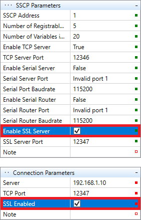
Securing the controller


Connecting inputs/outputs
In Mervis IDE you now have Unipi 1.1/Lite attached. Construction-wise, Unipi controllers consist of a computing module (Raspberry Pi in our case) and a circuit board with inputs and outputs. The board communicates with the computer using Modbus TCP and I²C. This is the reason why you need to set up two communication channels to control Unipi 1.1/1.1 Lite boards. The first channel is for controlling analog and digital I/Os via Modbus TCP protocol while the I²C channel controls relay outputs.
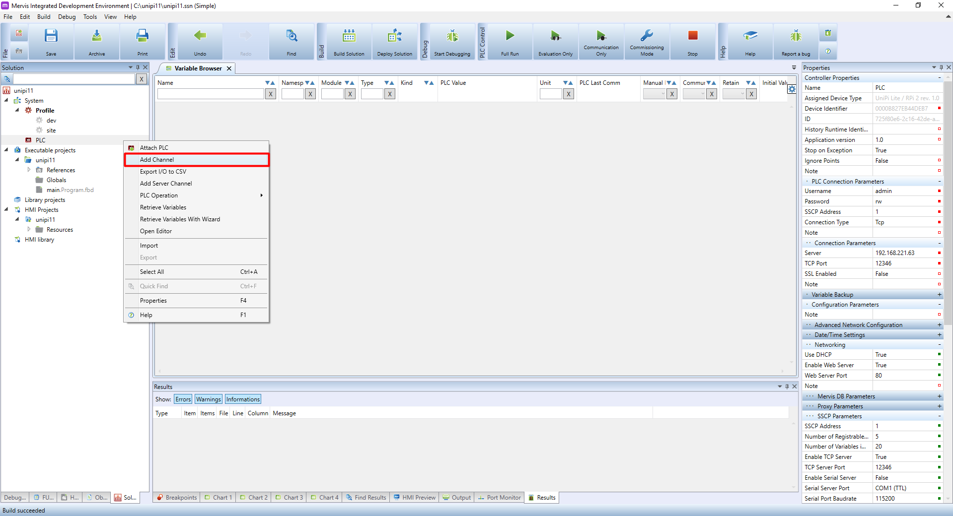
Add two communication channels to the PLC. TO add a channel right-click on the PLC name and then click on Add Channel. Repeat for the second channel.
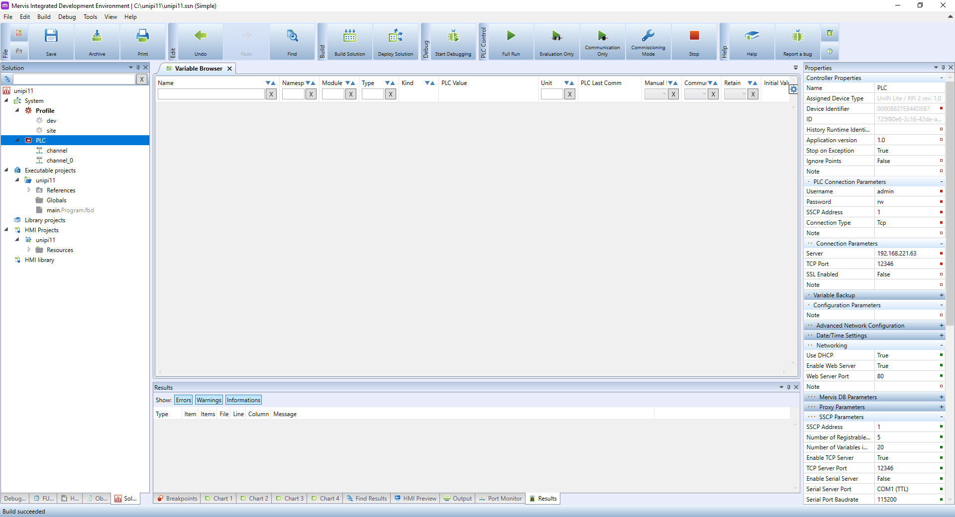
Two channels will appear below the PLC item.
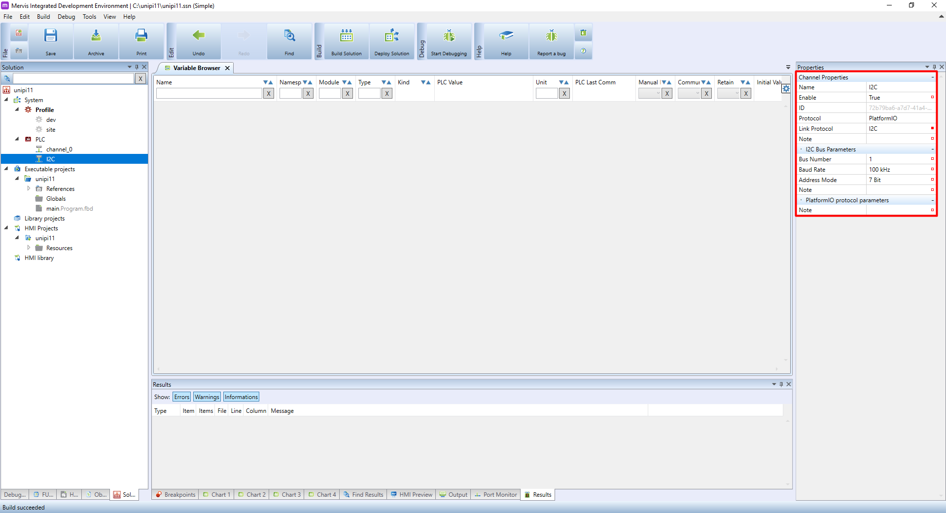
If you click on the first channel, its properties will appear in the right panel. The first item determines the channel's name; we recommend to give channels descriptive names - in this case, I²C will do.
Click on no protocol and select PlatformIO from the list. By doing so more options will appear - all you need to do here is to make sure the link protocol is set to I²C.
The first channel for relay outputs is already set.
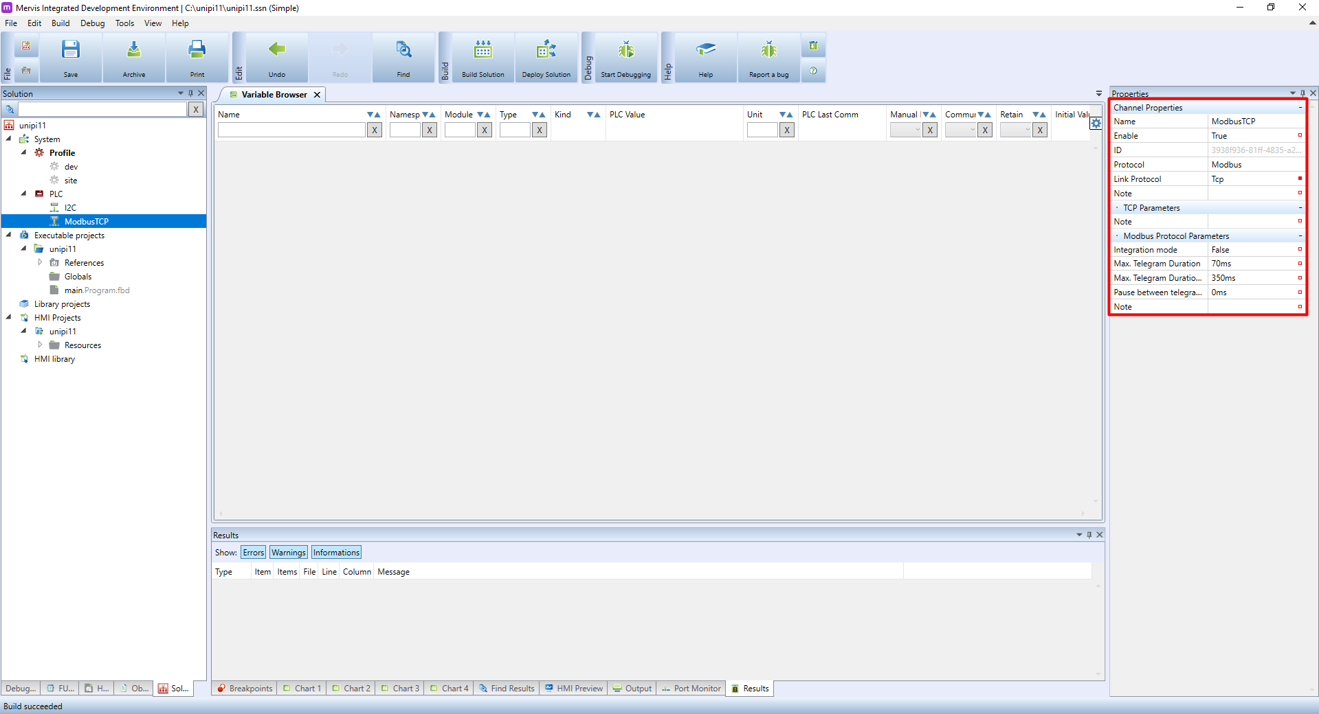
Now click on the second channel you created and give it an appropriate name. As the channel will communicate via Modbus TCP, we will simply name it ModbusTCP.
Then again click on no protocol and set the protocol to Modbus. More options will be displayed - again, just make sure the link protocol is set to TCP.
With both channels configured we can now move to add individual devices. These device definitions are different between Unipi 1.1 and Unipi 1.1 Lite, making the correct selection of definition necessary.
I²C
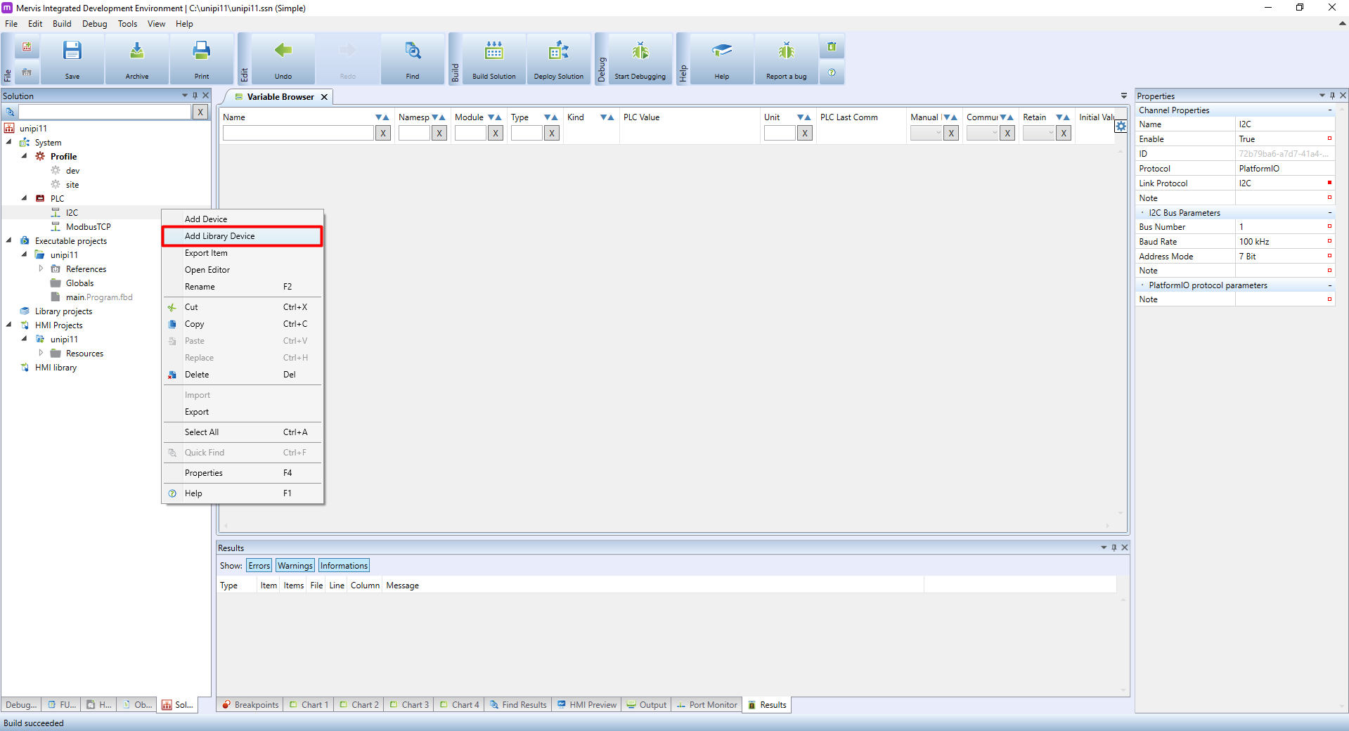
In the left panel right-click on the I²C channel. Select Add Library Device from the context menu.
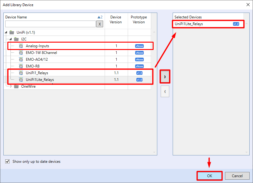
In the Add Library Device dialogue window you will see a list of devices. Find and expand the Unipi (v1.1) folder and move to the I²C subfolder. Select the suitable device definition accordingly (eg. Analog-Inputs + Unipi1_Relays for Unipi 1.1 and Unipi1Lite_Relay for Unipi 1.1 Lite). If you have the definition selected, click on the arrow icon ![]() to add the controller into the list of the selected device. After that, you need only to confirm by clicking on OK.
to add the controller into the list of the selected device. After that, you need only to confirm by clicking on OK.
ModbusTCP
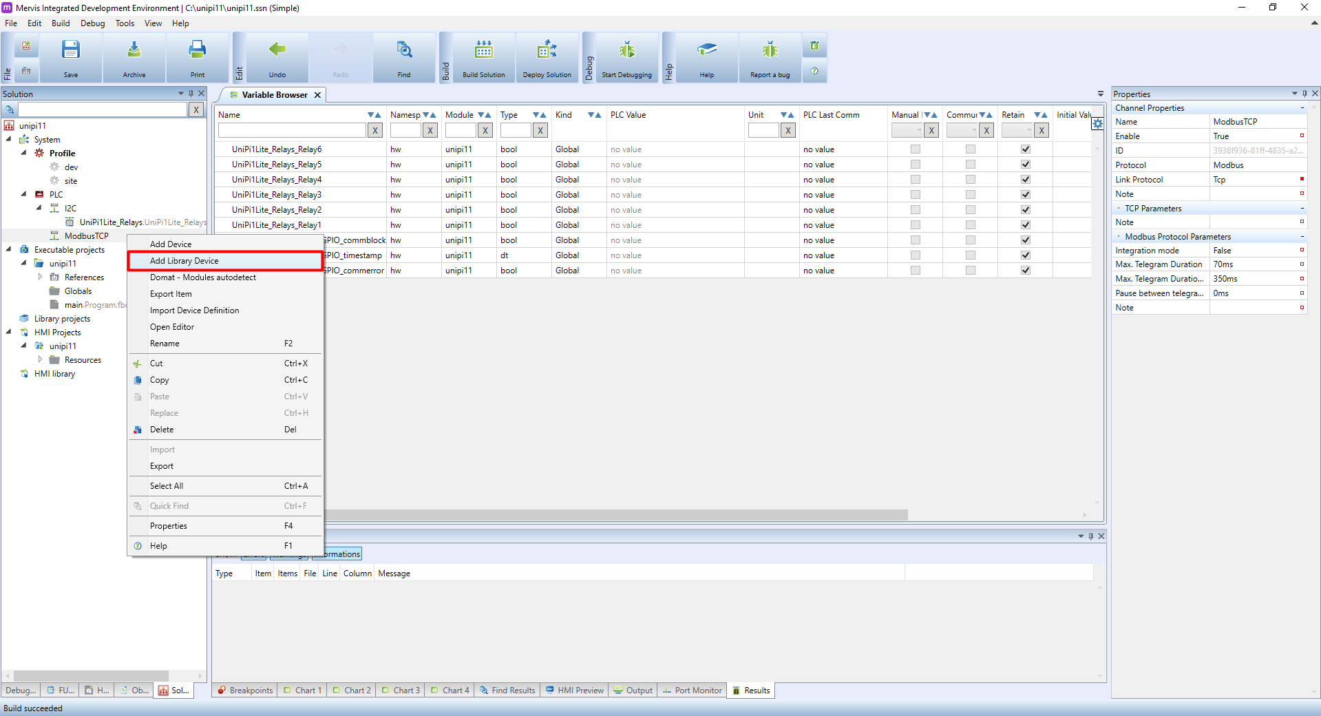
In the left panel right-click on the ModbusTCP channel. Select Add Library Device in the context menu.
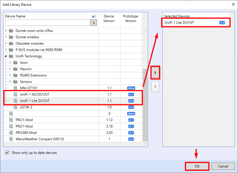
In the Add Library Device dialogue window a list of various devices will be displayed. Expand the Unipi technology folder and select the required definition depending on if you have Unipi 1.1 (Unipi 1 AO/DI/CNT) or Unipi 1.1 Lite (Unipi 1 Lite DI/CNT).
With the definition selected click on the arrow icon to add the controller into the list of selected devices. After that, you need only to confirm by clicking on OK.
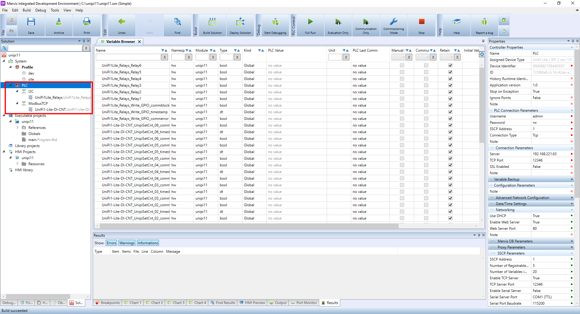
The new device will appear below the corresponding I²C / Modbus TCP channel.
Switching to Full Mode
As you created the solution in Simple Mode, you do not have access to some Mervis IDE functions such as history logs. The advantage of creating a project in Simple mode is that you create the basic structure of the project, including the creation of the main program main.program.fbd and the assignment of this program to the PLC task, so it is not necessary to set everything manually. Another advantage is that all data points in device definitions (e.g. in modbus tables) have automatically generated global variables. This is especially useful when getting to know the Mervis IDE to make everything a little easier.
With everything required configured, you can switch the solution to Full Mode.
Right-click on Solution Name (first tab) in the Solution panel in left menu. In the context menu click on Switch to Full Mode.

A warning will tell you the action is irreversible. Confirm by OK to continue.

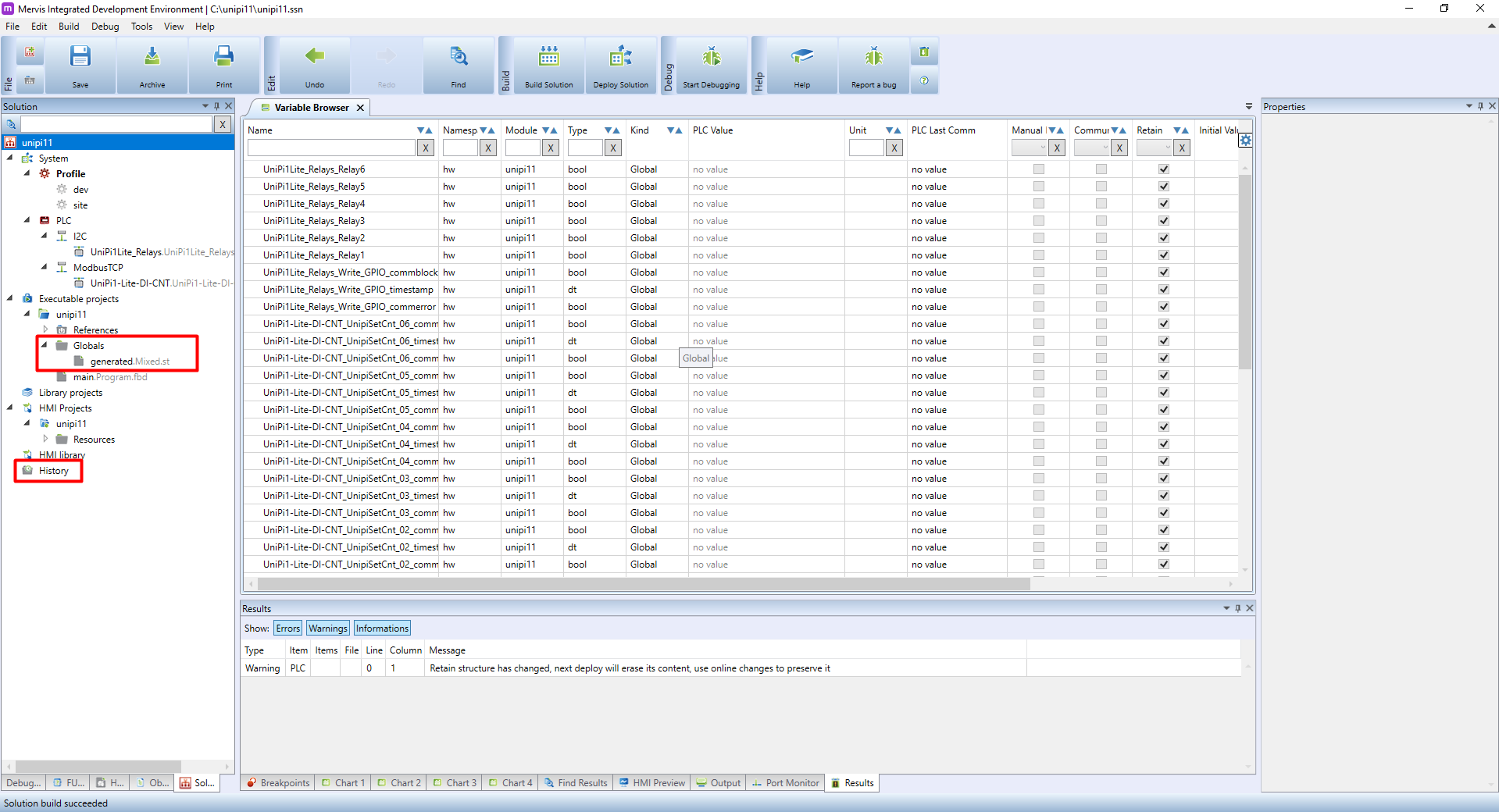
The result is you now have access to other functions. The most visible change occurred in the left panel - at its bottom, the History log item appeared. Executable Projects now also displays generated.Mixed.st file. This file contains variable definitions, in our case automatically generated by the Simple Mode. Don't delete, move or edit this file, its editing and creation are performed automatically. Autogen serves for automatic generation of variables from data points and can be applied to an entire device containing multiple data points, groups etc.
Building and Deploying the solution (project)
Solution building
Solution build compiles all executable projects, HMI interfaces, function libraries and HMI libraries into a single binary file used by the Mervis OS runtime. During the process, the system checks the validity of all configurations and will warn you if anything would prevent a successful compilation.
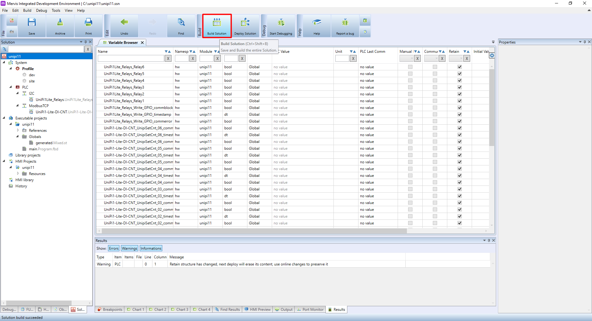
To start the compilation go to the upper ribbon and click on Build Solution.
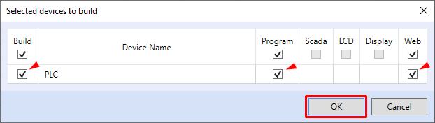
A Selected Devices to Build window will appear - a list of connected controllers the project can be compiled for. By default, the system selects all available controllers, terminals or web interfaces. Confirm your selection by clicking on OK.
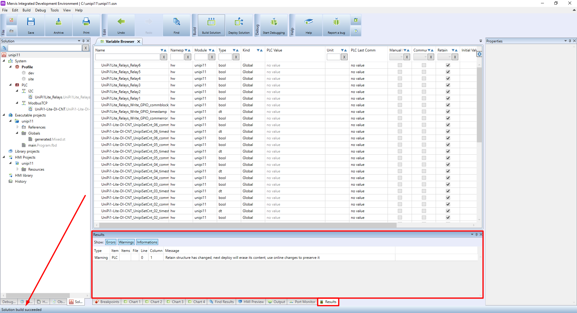
This step will start the compilation itself. The Results tab on the bottom panel will display any messages displayed during the compilation. The compilation progress can be monitored in the status bar. If you performed all the instructions above correctly, the compilation should be completed successfully and the status bar should display “Solution build succeeded”.
Deploying the solution
Deploying a solution means: compiling and then uploading the created binary file to the controller and running it in Full run. Click Deploy Solution on upper ribbon to deploy the solution.

As with the solution build, Deploy Solution will also display a list of controllers to deploy the solution to. Confirm your selection by clicking on OK.

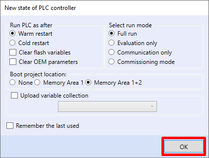
The last step in deploying a solution is to set a new controller status. There are multiple options, but for the purposes of this tutorial, leave the default options and click OK.
Switching a relay
With the project good to go, we will now move to create your first control program. Its purpose will be to periodically switch the Relay1 output. To switch the output will require setting Relay1 to alternate between True and False states. The basic executable project was generated automatically in Simple Mode, thanks to which we now have the main program available for creating the logic. In the left panel double-click on main.Program.fbd.
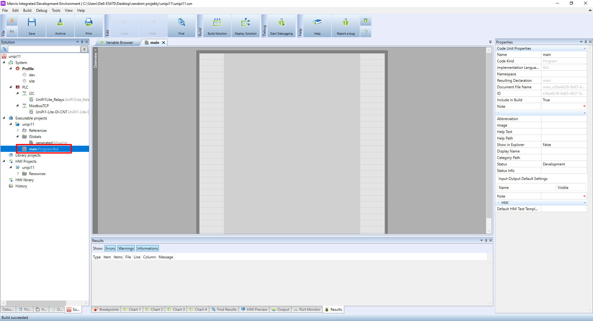
A program window will appear in the main window.
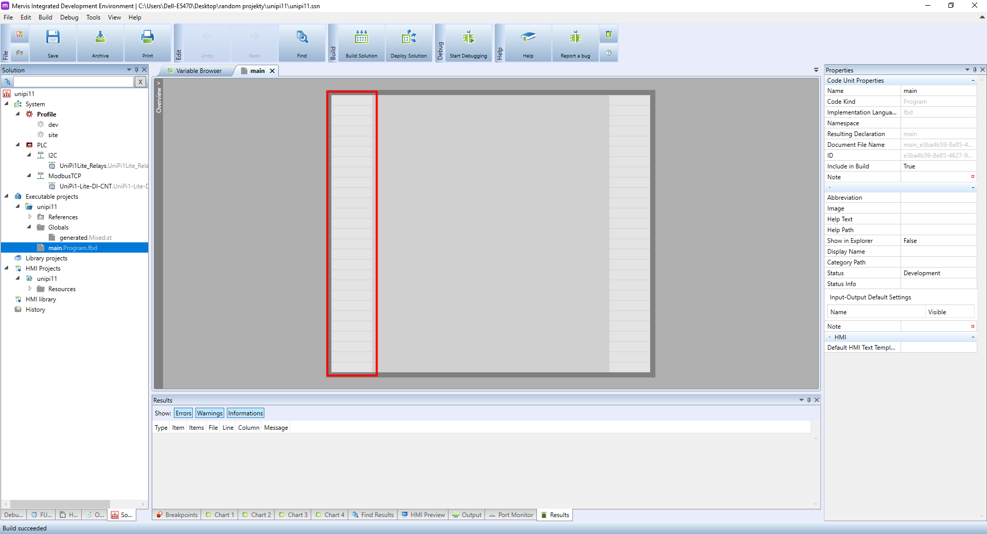
The FUPLA programming space is divided into three sections - the left side is reserved for Inputs with each grey box available for placing a single input variable.
The middle section is called logic section and will be used for the programming itself.

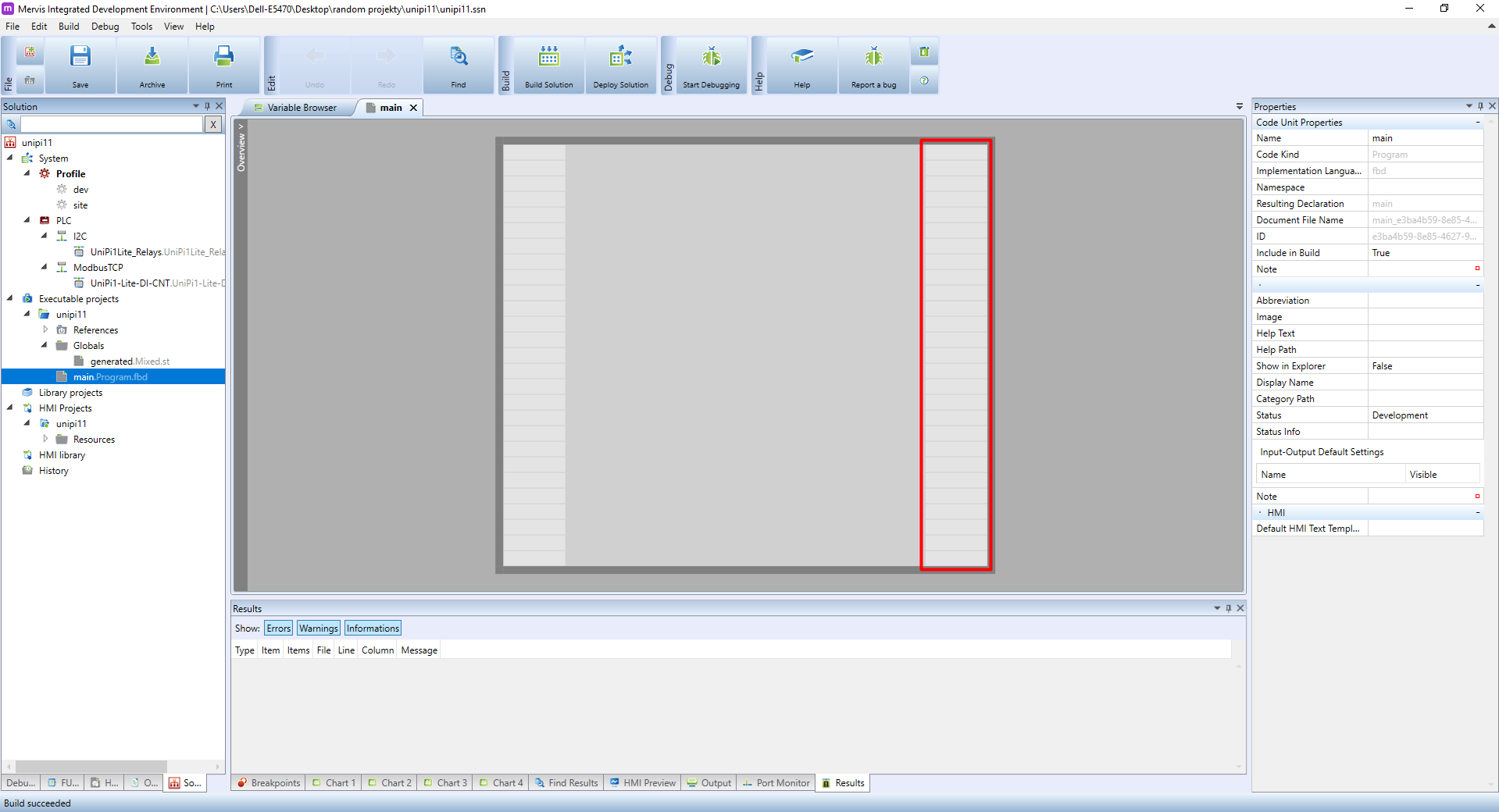
And finally, the right section is for placing outputs. As with the outputs, there is a number of grey boxes for placing output variables.
For the demonstration and testing purposes you can create a simple logic for switching the above-mentioned Relay1. The entire logic will consist of predefined function blocks (FB) available in Mervis libraries. Each FB is designed for one specific function and consists of inputs, internal logic and outputs. The values on the inputs are processed by the internal logic and it then projects the result on the outputs, which can be connected to the inputs of other FBs or to the hardware outputs.
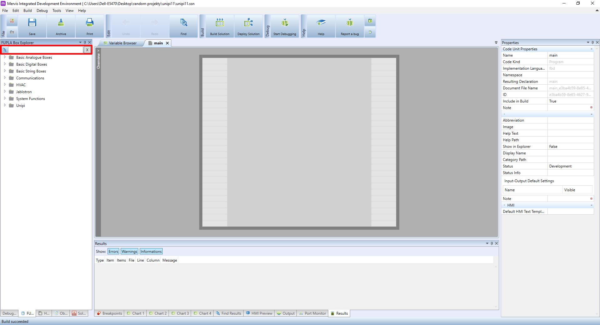
Click on FUPLA Box Explorer - you can find it among tabs at the left panel's bottom edge.

The left panel's upper edge includes a search column for quick and easy search for blocks predefined by Mervis.
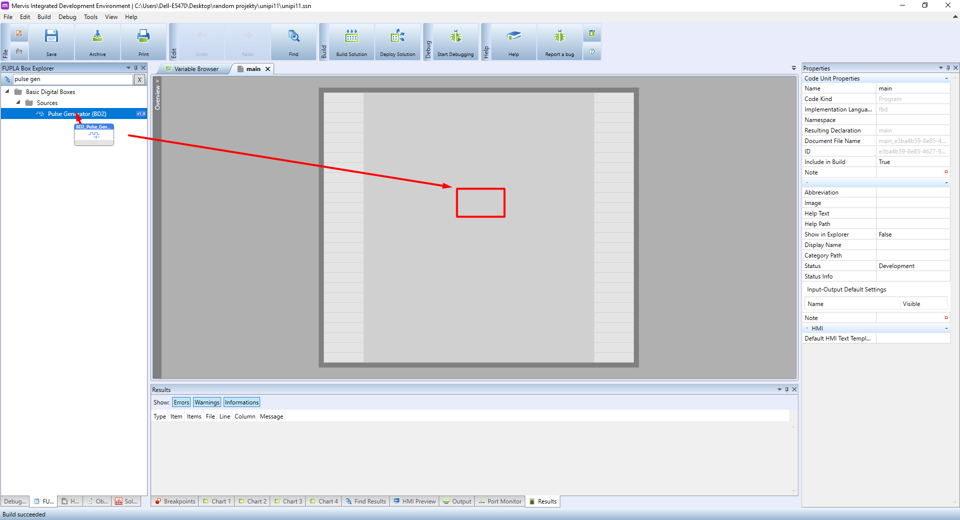
Let's find a pulse generator. Enter pulse generator into the search column. As the system searches through function blocks in real-time, the number of results will gradually decrease. After entering the entire name of the block, only a single result will remain - the Pulse Generator (BD2) block. Click on it, hold the mouse button and drag the block over to the logic section. Then place the block by releasing the button.
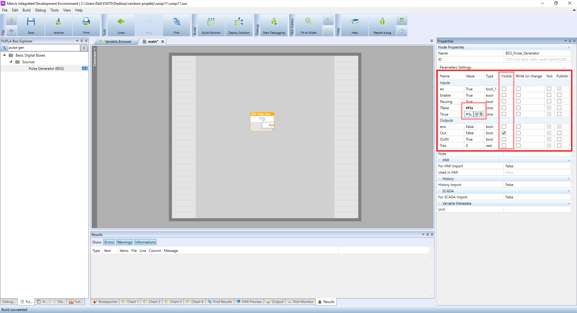
The BD2 Pulse Generator block contains simple logic - by default, the Out output periodically switches between True and False every second. Let's take a closer look at its inputs. Enable input and outputs Out and OutN are visible on the FB itself. However, if you double-click the block it will change its colour to yellow - an indication of selection. The Properties panel will then display a complete list of inputs and outputs. As you can see there are many more inputs than those visible in the main window, as most of the inputs/outputs are hidden by default. Visibility of the individual inputs/outputs can be toggled by the Visible property. As we need only the pulse generator's Out output, un-check the Visible box for all inputs/outputs except Out. Bear in mind Mervis IDE does not allow any unconnected inputs in the logic section and any attempt to build such a solution will fail. The last step is to set 5s interval for Ttrue and Tfalse - that will ensure the relay will switch open/close every 5 seconds.
Note:: you can display additional info about any block by selecting it and pressing F1 to open the help page for the block.
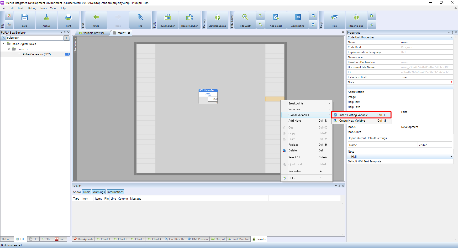
You now need to connect the pulse generator's output to Relay1 input. Right-click on input section to display a context menu, move the cursor over Global Variables and from the submenu choose Insert existing variable.
In the Insert existing variable, a list of all available variables, inputs and outputs of your controller will be displayed. If the list is nearly empty, you probably did not use Autogen to define variables available for your PLC. In that case, right-click on devices in both I²C and Modbus TCP channels and click on Set autogen in the context menu.
If you followed the guide closely, Simple Mode already generated all variables for the program.
Autogen generates variables based on all available or selected data points of inputs and outputs. That means we need to generate this list to use the PLC's inputs/outputs in the program.
Alternatively, you can double-click on Unipi1_Relays / Unipi1Lite_Relays and set the Autogen manually by right-clicking on the Relay1 data point and selecting Set Autogen in the context menu. You can use this method for other devices as well.
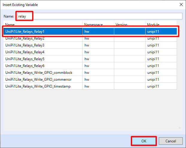
In the Insert existing variable dialogue window a long list of available variables will appear. You can search for variables manually, or you can try to find it by its name. For this tutorial, we will enter Relay, as all relays on Unipi 1.1/1.1 Lite are named as such. On Unipi 1.1 you have 8 changeover relays available, with Unipi 1.1 Lite having only 6 of them. A relay is always named RelayN with N representing a specific relay number (1-8). Click on Relay1 and confirm by clicking on OK.
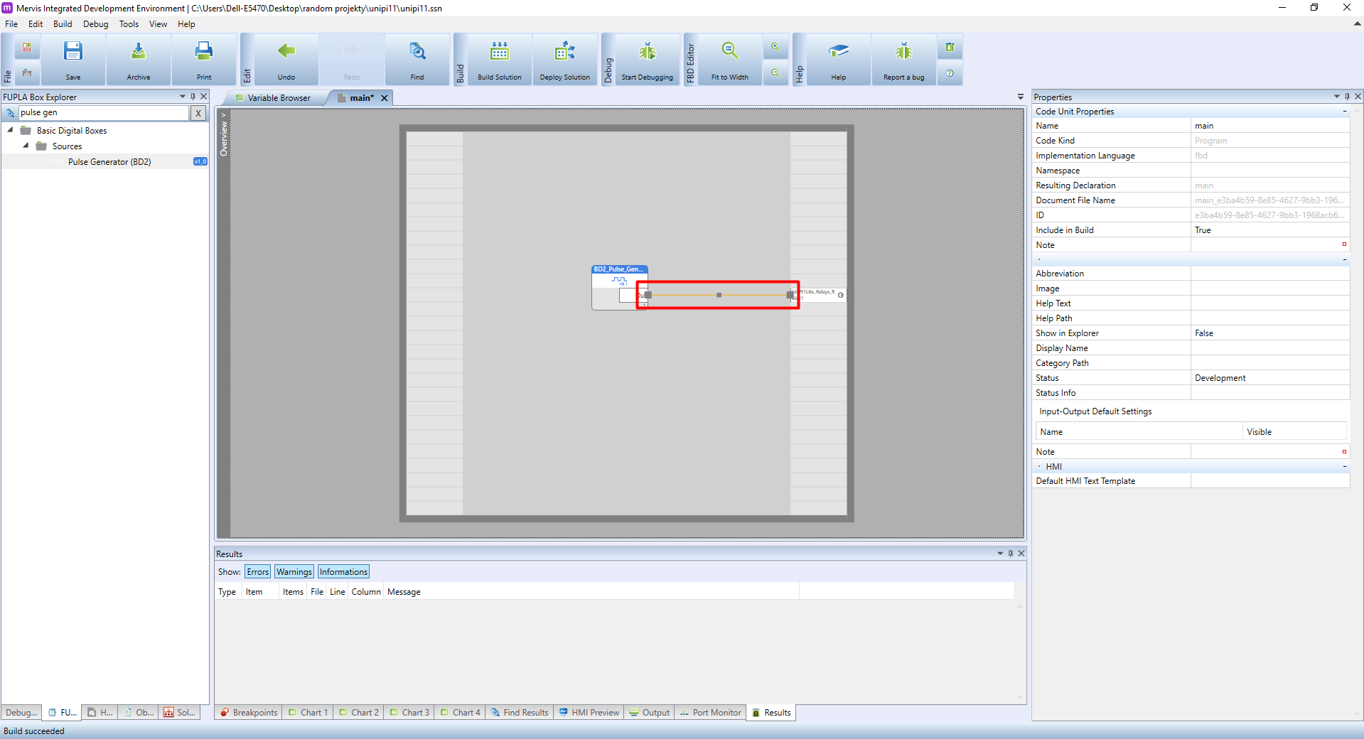
The output variable appears in the output section at the marked location. Now it is necessary to connect the output of the function block of the pulse generator with the variable Relay1. Move the cursor to the black dot next to the Out output name of the pulse generator block. A small box will appear containing information about the type of output.
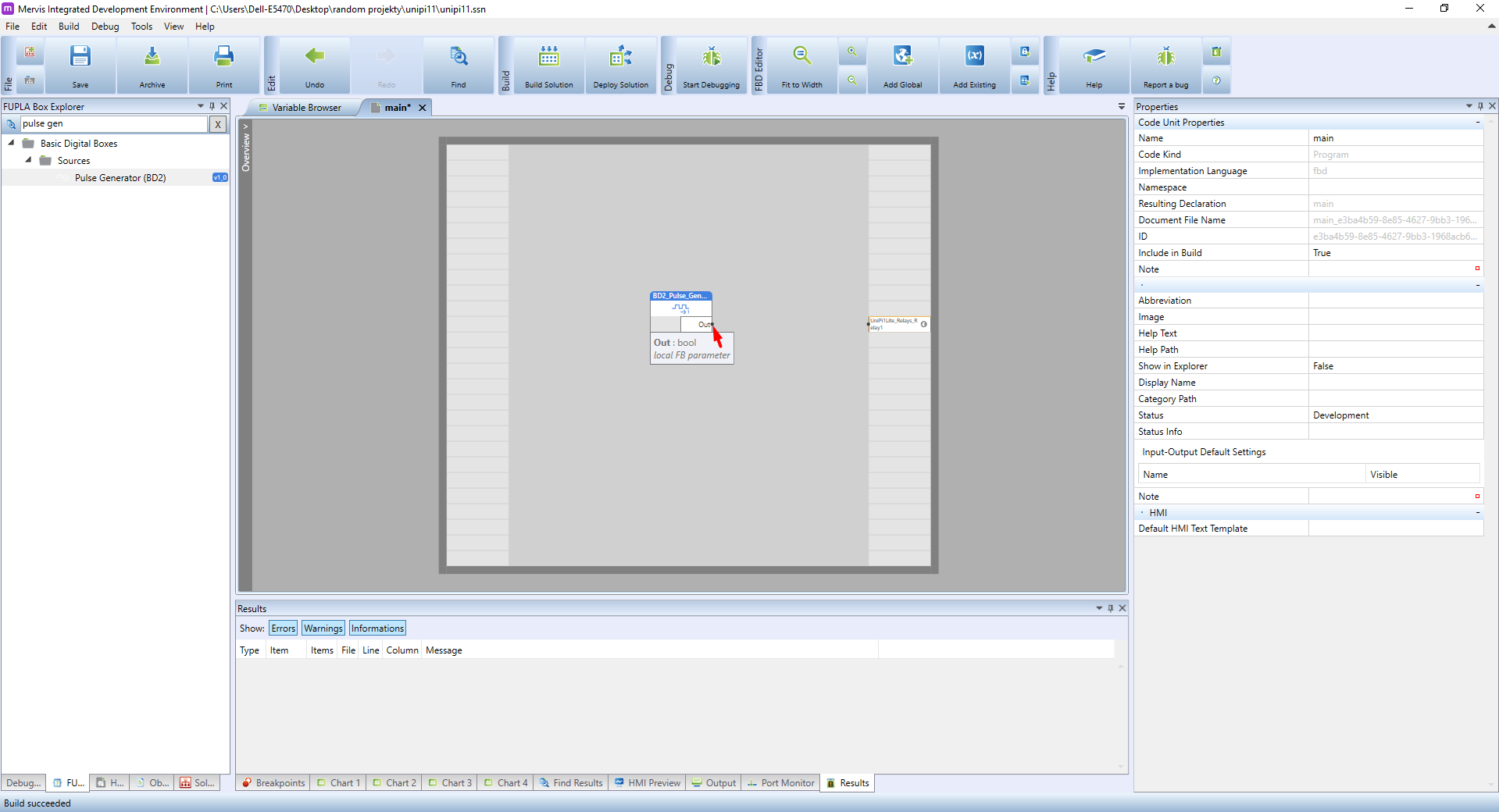
Click on the dot, hold the mouse button and move the cursor to a similar black dot placed next to the Relay1's name. A green line will appear between both outputs. After releasing the mouse button, the line will change to orange.
Now you can Build Solution - see Building and uploading the solution. If you did everything right, a Build succeeded message will appear in the status bar. Warning messages displayed in the Results tab can be safely ignored.
If the build succeeded and you followed the instructions above correctly, you can upload the solution into the controller - see Building and uploading the solution.
Upon deploying the solution the relay output Relay1 will be switched every 5 seconds.
Congratulations, your first Unipi 1.1 project is now complete!