This is an old revision of the document!
 This page is not fully translated, yet. Please help completing the translation.
(remove this paragraph once the translation is finished)


The production of Unipi Axon units was discontinued and no further software updates will be released. The Axon line was replaced by the Unipi Patron.
Digital inputs
Digital inputs serve for an indication of TRUE/FALSE logic states and can be also used as counters to collect data from pulse meters, monitor engine revolutions etc. Another possible application is to connect input and output using the DirectSwitch function.

Log. 1 (switched on) on input is indicated by LED with the corresponding marking matching the input label.
The software detects TRUE state if the input voltage between the given DIx and DIGND terminals is in range of 7-35 V⎓. If the voltage decreases below 3 V⎓, the FALSE state is indicated. The voltage between 3-7 V⎓ is detected as a non-defined state.
Connection
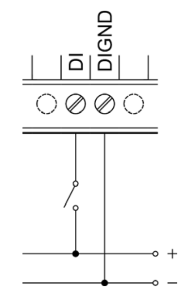
Each connector with digital inputs features a common DIGND terminal for connection of DC power source negative pole. The positive pole of the power supply is to be connected to the DIx or DIy.x terminal through the connected external device. See the following image for illustration:
Please note:
For connection of external devices to digital inputs, we recommend using a different (separate) power supply from the one used to power the device (unit/Extension) in order to retain galvanic isolation. Each digital input group also feature a DIGND terminal added specifically for connection of the separate power supply negative pole.
Special functions
Aside from the standard inputs and outputs, Axon controllers also feature additional functions for broadening the possible applications, performance optimization and monitoring of the entire project. These functions are calculated directly by the I/O section's microprocessors, making them independent on the control software.
Counter input
Direct Switch
The DirectSwitch function can be used on any unit or extension module equipped with digital inputs and digital or relay outputs within a single section.
This function allows logical connection of digital input to digital output or relay output to automatically perform one of the available operation. DirectSwitch is independent on the control software running on unit and is suitable for control of lighting or any other time-critical applications (typically, the output response time matches the input response).
The function can be configured for one of three modes:
- Copy - input state is copied to the output
- Inverse copy - negated state of the input is set on the output
- Switch - if a rising edge is detected on the input, the output state is negated
- (Block - disables DirectSwitch)
Please note:
DirectSwitch function can be configured only for the corresponding input and output, ie. only for DIy.x input and DOy.x (ROy.x) output, where x and y (if the y is given) numbers must match. It is not possible to use DirectSwitch simultaneously for input and output with mismatched labels, eg. DIx.y and DOv.z. It is also not possible to use the function for a single input and multiple outputs at the same time.
Attention:
If DirectSwitch is applied to an output, it is not possible to write onto output (DO) in a regular way. Instead, you need to set the ForceOutput register to TRUE for approx. 1 second.
Technical parameters
| Input type | SINK |
| Input terminal | DI |
| Common ground | DIGND |
| Log. 0 | < 3 V DC |
| Log. 1 | > 7 V DC |
| Maximum voltage | 35 V DC |
| Non-defined state | 3-7 V DC |
| Input resistance for TRUE | 6 200 Ω |
| Voltage drop on DI diode | 1.2 V |
| Minimum pulse length | 20 μs |
| 0–>1 / 1–>0 delay | Typ. 20 μs / 60 μs |
| Maximum CNT counter input frequency | 10 kHz |
| LED indication | Yes |
| Galvanic isolation (pulse) | 1.5 kVAC between DI and all other circuits |


