This is an old revision of the document!
Relay outputs

Special functions
Direct Switch
The DirectSwitch function can be used on any unit or extension module equipped with digital inputs and digital or relay outputs within a single section.
This function allows logical connection of digital input to digital output or relay output to automatically perform one of the available operation. DirectSwitch is independent on the control software running on unit and is suitable for control of lighting or any other time-critical applications (typically, the output response time matches the input response).
The function can be configured for one of three modes:
- Copy - input state is copied to the output
- Inverse copy - negated state of the input is set on the output
- Switch - if a rising edge is detected on the input, the output state is negated
- (Block - disables DirectSwitch)


Please note:
DirectSwitch function can be configured only for the corresponding input and output, ie. only for DIy.x input and DOy.x (ROy.x) output, where x and y (if the y is given) numbers must match. It is not possible to use DirectSwitch simultaneously for input and output with mismatched labels, eg. DIx.y and DOv.z. It is also not possible to use the function for a single input and multiple outputs at the same time.

Attention:
If DirectSwitch is applied to an output, it is not possible to write onto output (DO) in a regular way. Instead, you need to set the ForceOutput register to TRUE for approx. 1 second.
Default configuration
This function is used to save the current configuration of the section (extension module) into its memory. In the case of power cycle of the device or reboot of the section (extension module), the stored configuration is loaded and applied. This functionality is also known as “copy
running-config to startup-config”.
| Stored data | Default configuration |
|---|---|
| Output value | FALSE |
Master Watchdog
This function runs on the section's (extension module's) microprocessor and continuously monitor the commands from the application running on the unit. If no commands are detected within a configured time (MWD Timeout), the section's (extension module's) processor automatically reboots and reverts to the default configuration described above. This function ensures a safe configuration is set in case of emergency situations (unit failure, communication error or software issues) to prevent damage to controlled devices or any hazards to personnel.
Technical parameters
Please note: The data below represent a selection of the most important parameters and serve only as a quick reference.

Detailed information can be found in the product datasheet provided by the relay manufacturer: FTR-F3AA024E-HA
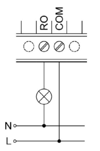
| Output type | Electromechanic non-shielded relay |
| Output terminal | RO |
| Common terminal | COM |
| Contact type | Normally open (SPST-NO) |
| Used relay type | FTR-F3AA024E-HA |
| Maximum switching voltage | 250 V AC 30 V DC |
| Maximum switching current | 5 A |
| Maximum common terminal current | 10 A |
| Short-term current overload | 5 A |
| Mechanical lifespan | 5 000 000 |
| Electrical lifespan | Up to 100 000 (according to the connected load) |
| Operate/release time | 10 ms |
| Designed for load character | AC-15, DC-13 (resistive) |
| Load handling | External (RC, varistor, diode, thermistor) |
| Short circuit protection | No |
| Overvoltage protection | No |
| LED indication | Yes |
| Galvanic isolation | Yes (Basic) |
| Insulation voltage (pulse) | 2500 V between RO and RO 4000 V between RO and all other circuits |


