This is an old revision of the document!
Digital inputs

Special functions
Counter input
One of the most interesting functions is counter input - a high-speed rising edge counter independent on the control software. Simply put, the counter can very accurately detect even very short pulses.
Counter inputs are suitable especially for collecting data from energy meters, water meters, gas meters and other pulse meters installed in HVAC systems. They are also useful for reading engine revolutions. For this purpose, Unipi units feature 64-bit registers. When the maximum value of the counter (4 294 967 295) is exceeded, the counter resets to 0. Counter inputs can be used at up to 10 kHz frequency; in the Mervis IDE library devices, they are labelled as CNT inputs.
Caution:
Counters on Unipi 1.1 and 1.1 Lite are reset when the power supply is unplugged. This function must be configured in the control SW.
Jumper settings:
An external power supply can be used to power digital inputs using a correct configuration of jumpers JP2 - JP5. Using an external power supply also includes galvanic isolation of digital inputs. The Unipi 1.1 must be unplugged from power during jumper configuration. After finishing the adjustments and connecting the external power source's negative pole (see below), you can plug back the board's power.
Only the combinations described below are supported. Any other configuration may cause damage to the device or connected peripherals.
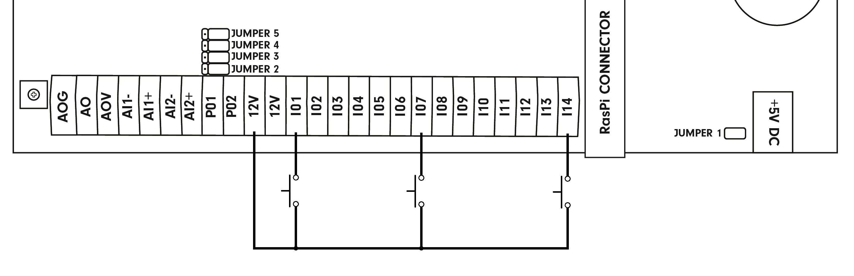
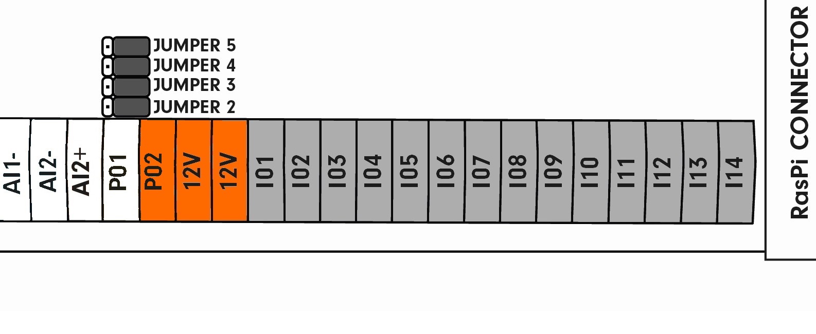
This picture shows the default jumper settings. Digital inputs are connected to the internal 12 V⎓ power supply. The P02 terminal now provides 12 V⎓ voltage.
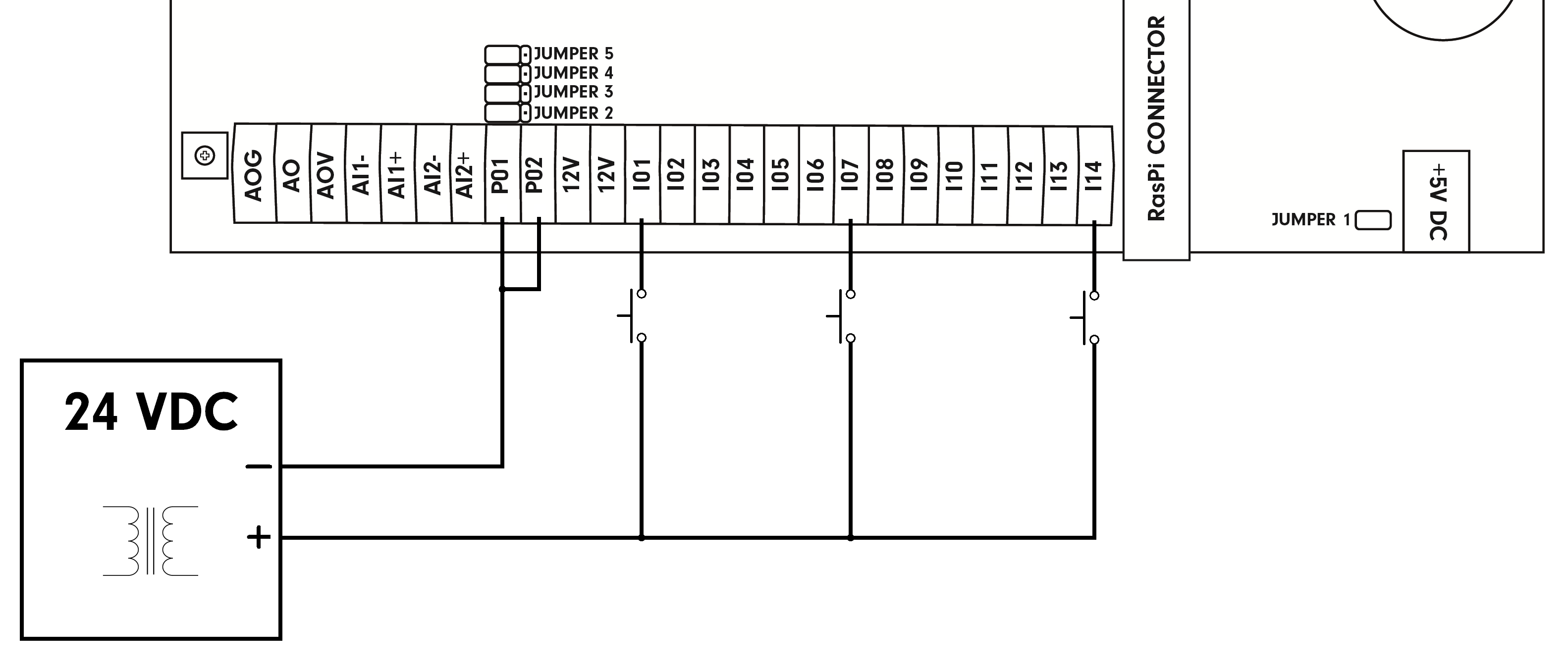
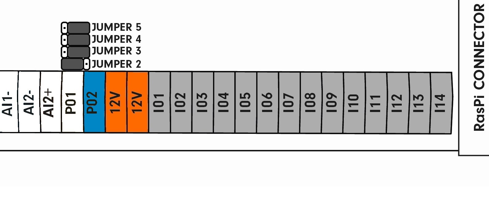
The JP2 jumper is moved away from the Raspberry Pi with digital inputs still connected to the 12 V⎓ internal power supply. The P02 terminal now acts as GND for the entire board:
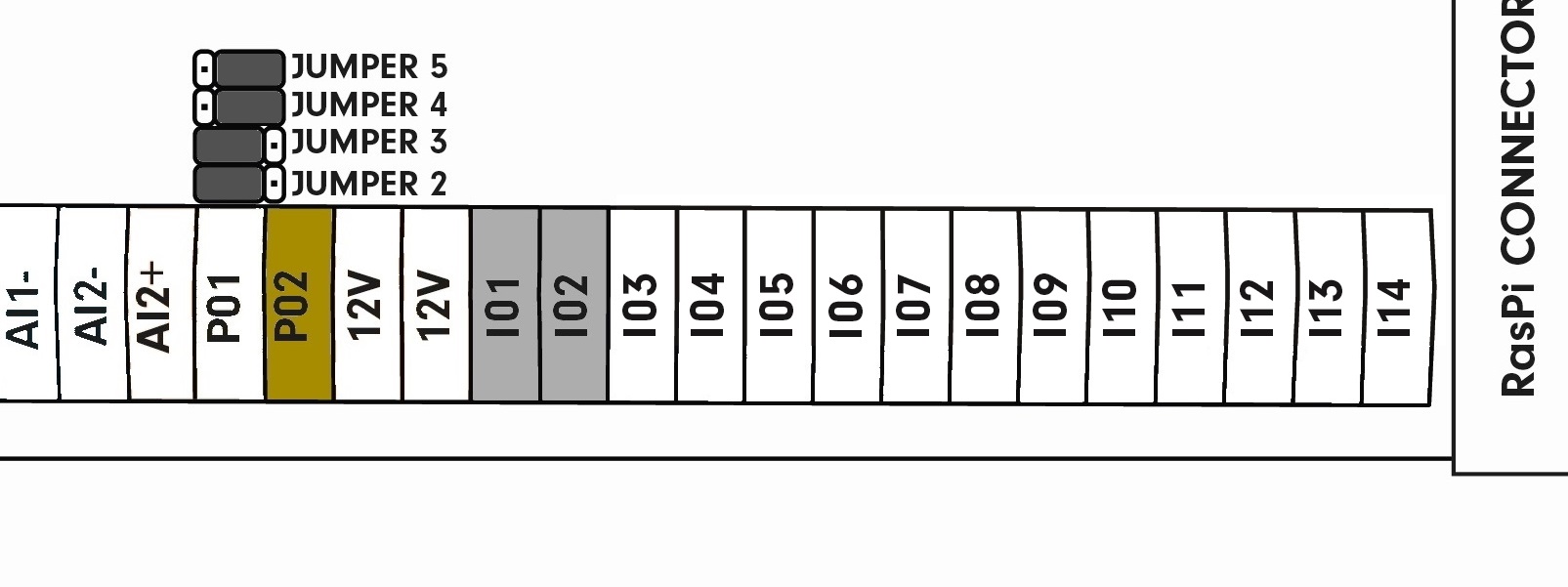
Jumpers JP2 and JP3 are moved, digital inputs I01 and I02 are ready for connection of an external power supply. Terminals I03 to I14 are connected to the internal 12 V⎓ power supply. The P02 terminal can be now used to connect the external power supply's negative pole for inputs I01 and I02:
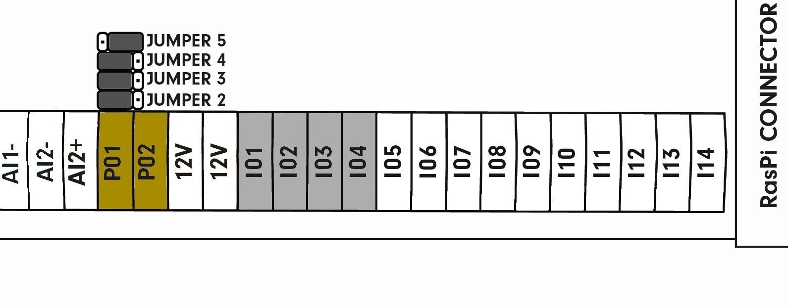
Jumpers JP2, JP3 and JP4 are moved, digital inputs I01 to I04 are ready for connection of an external power source. Terminals I05 to I14 are connected to the internal 12 V⎓ power supply. The P02 terminal serves for connection of the external power supply's negative pole for I01 and I02. The I01 terminal can be now used to connect the negative pole of an external power supply for I03 and I04. Terminals P01 and P02 and their corresponding inputs are mutually isolated:
Jumpers JP2, JP3, JP4 and JP5 are moved, all digital terminals are ready for connection of an external power supply. The P02 terminal serves for connection of the external power supply's negative pole for I01 and I02. The P01 terminal now serves for connecting the external power supply's negative pole for outputs I03 to I14. Terminals P01 and P02 and their corresponding inputs are mutually isolated:

Technical parameters
| Input type | SINK |
| Input terminals | Ixx (xx represents the terminal's number) |
| Number of inputs | 14* |
| Maximum voltage for log. 0 | 3 V DC |
| Minimum voltage for log. 1 | 7 V DC |
| Maximum voltage | 24 V DC |
| Configurable terminals | P01, P02 |
| Internal 12 V DC power supply positive pole (only for DI, AI, and AO) | 12 V |
| Galvanic isolation | Yes (if an external power supply is used) |