Digital inputs
Digital inputs serve for an indication of TRUE/FALSE logic states.
Unipi 1.1
TRUE logic state (switched on) is indicated by the corresponding LED placed beyond the inputs.
Note:
For connecting external devices to digital inputs, we recommend using a different (separate) power supply in order to retain galvanic isolation.
The software detects TRUE state if the input voltage between the given DIx and DIGND terminals is in range of 7-24 V⎓. If the voltage decreases below 3 V⎓, the FALSE state is indicated. The voltage between 3-7 V⎓ is detected as a non-defined state.
Connection
Unipi 1.1 features the option to connect internal and/or external power supply for digital inputs. By default, the internal source is sufficient. However, if you need to connect an external reference ground, you can do so by using P01 and P02 terminals after properly setting jumpers JP2-JP5. Always set the jumpers first and only then connect the power supply's negative pole see the guide below. The power supply's positive pole is to be connected through the external device using the Ixx terminal, as described by the following pictures:
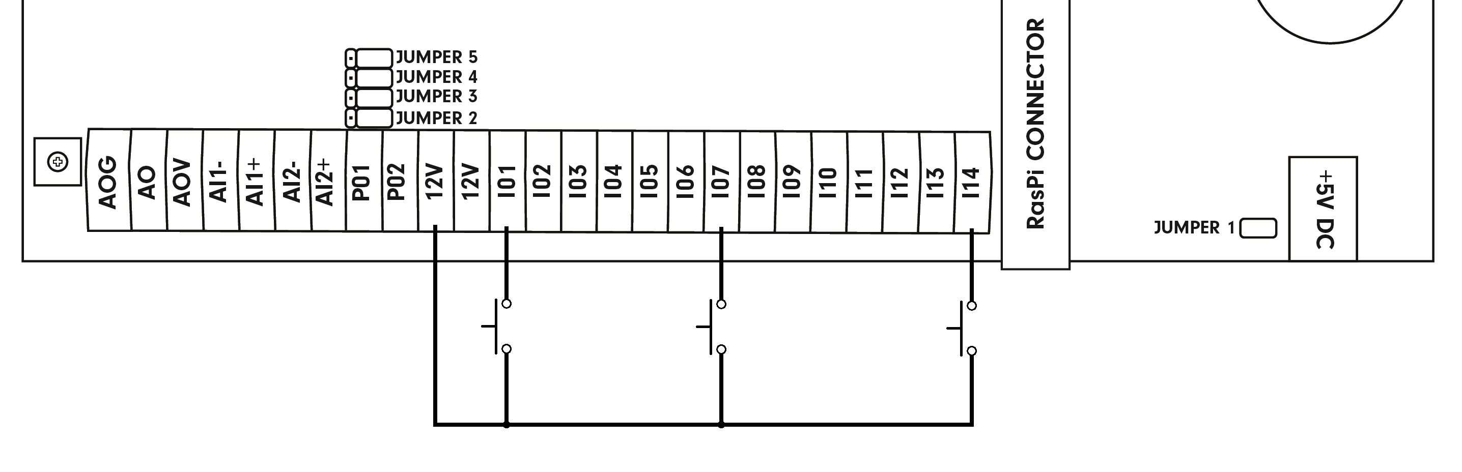
DI connection with the internal power supply:
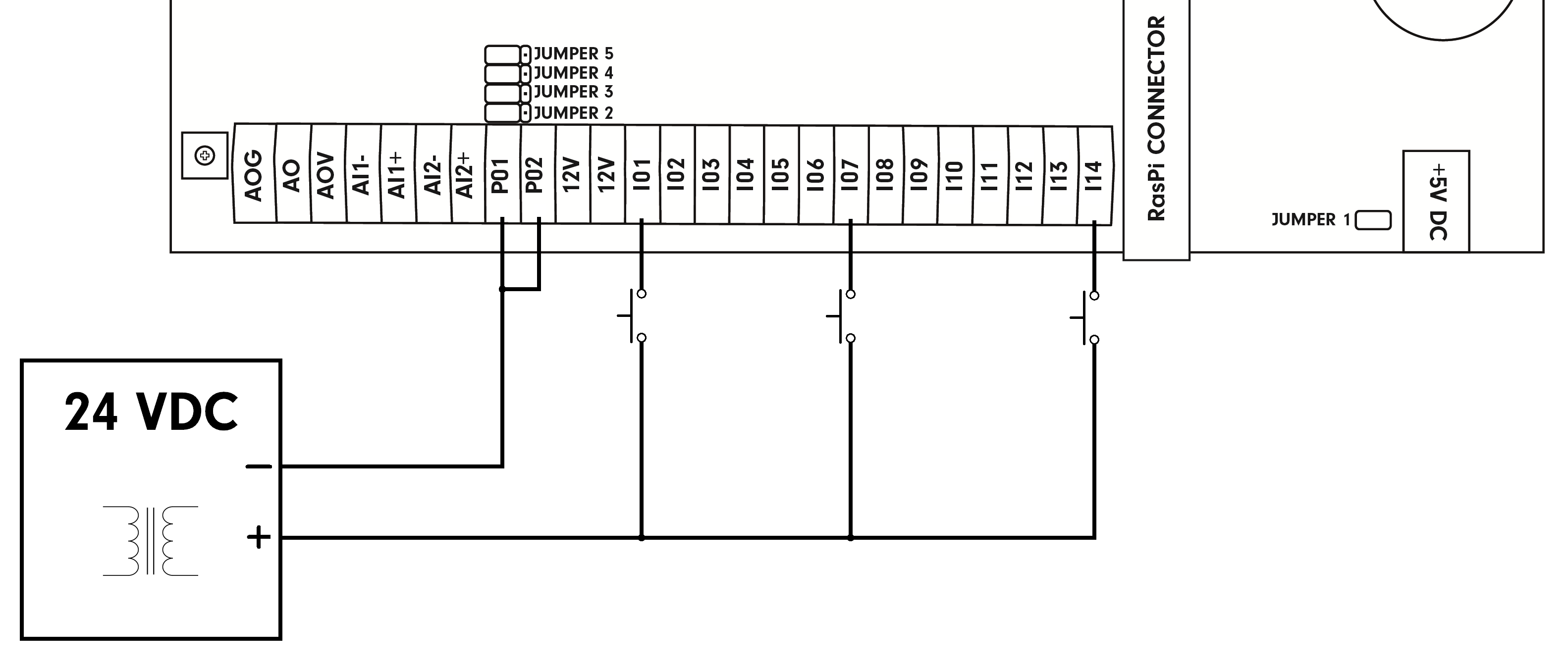
DI connection with the external power supply:
Notice the settings of jumpers JP2 - JP5.
DI connection with both the internal and external power supply:
Notice the settings of jumpers JP2 - JP5.

Use of clamps
Use of clamps with the original WAGO tool.
Use clamps with a small flat-blade screwdriver.
Special functions
Jumper settings:
An external power supply can be used to power digital inputs using a correct configuration of jumpers JP2 - JP5. Using an external power supply also includes galvanic isolation of digital inputs. The Unipi 1.1 must be unplugged from power during jumper configuration. After finishing the adjustments and connecting the external power source's negative pole (see below), you can plug back the board's power.
Only the combinations described below are supported. Any other configuration may cause damage to the device or connected peripherals.
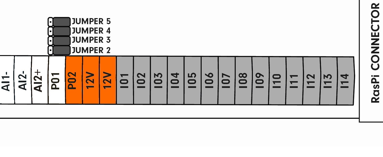
This picture shows the default jumper settings. Digital inputs are connected to the internal 12 V⎓ power supply. The P02 terminal now provides 12 V⎓ voltage.
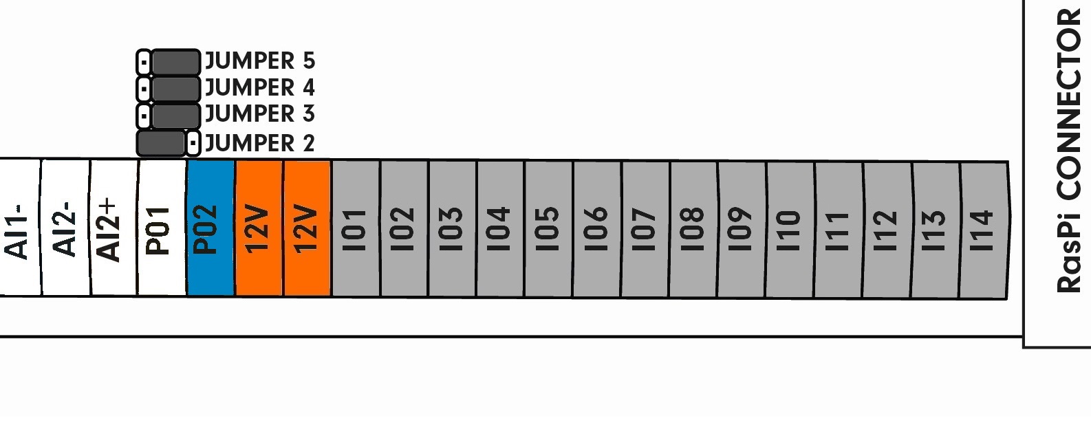
The JP2 jumper is moved away from the Raspberry Pi with digital inputs still connected to the 12 V⎓ internal power supply. The P02 terminal now acts as GND for the entire board:
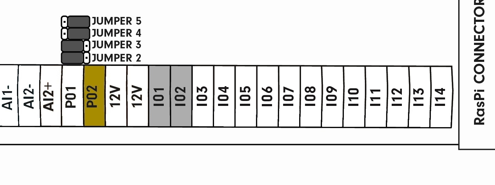
Jumpers JP2 and JP3 are moved, digital inputs I01 and I02 are ready for connection of an external power supply. Terminals I03 to I14 are connected to the internal 12 V⎓ power supply. The P02 terminal can be now used to connect the external power supply's negative pole for inputs I01 and I02:
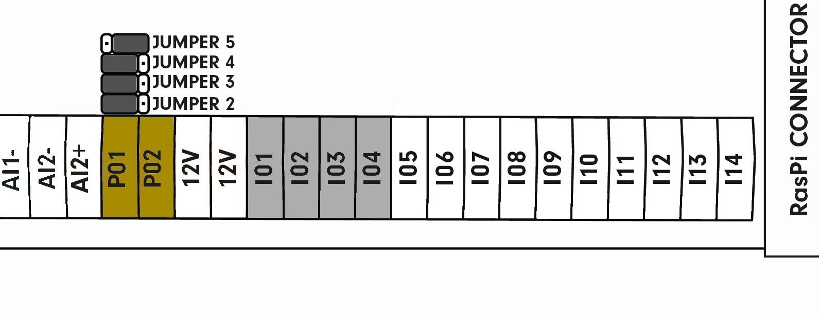
Jumpers JP2, JP3 and JP4 are moved, digital inputs I01 to I04 are ready for connection of an external power source. Terminals I05 to I14 are connected to the internal 12 V⎓ power supply. The P02 terminal serves for connection of the external power supply's negative pole for I01 and I02. The I01 terminal can be now used to connect the negative pole of an external power supply for I03 and I04. Terminals P01 and P02 and their corresponding inputs are mutually isolated:
Jumpers JP2, JP3, JP4 and JP5 are moved, all digital terminals are ready for connection of an external power supply. The P02 terminal serves for connection of the external power supply's negative pole for I01 and I02. The P01 terminal now serves for connecting the external power supply's negative pole for outputs I03 to I14. Terminals P01 and P02 and their corresponding inputs are mutually isolated:

Using I13 and I14 on the Unipi 1.1
The default cable used to interconnect the Unipi 1.1 board and the Raspberry Pi computer does not support digital inputs 13 and 14. That means a separate connection is necessary for their use.
The picture below shows the P5 header on the Unipi board. Pins for IN14 and IN15 inputs are highlighted by a red rectangle.

However, you can also use any unused GPIO for connecting the pins. After the connection, you need to edit the evok.conf file accordingly.
| RPi pin header | RPi function | Unipi P5 header | Unipi function |
| 27 | (GPIO28)ID_SD | 5 | I2C0 data |
| 28 | (GPIO29)ID_SC | 6 | I2C0 Clk |
| 29 | GPIO5 | 3 | I13 |
| 31 | GPIO6 | 4 | I14 |
| x | x | 7 | 3V3 |
| x | x | 8 | 5V |
| x | x | 1.2 | GND |
GND connectors are not required. The 3V3 connector is required only if the second I2C bus connector is used
Technical parameters
| Input type | SINK |
| Input terminals | Ixx (xx represents the terminal's number) |
| Number of inputs | 14* |
| Maximum voltage for log. 0 | 3 V DC |
| Minimum voltage for log. 1 | 7 V DC |
| Maximum voltage | 24 V DC |
| Configurable terminals | P01, P02 |
| Internal 12 V DC power supply positive pole (only for DI, AI, and AO) | 12 V |
| Galvanic isolation | Yes (if an external power supply is used) |