Digital outputs
Digital outputs (semiconductive, connected as open collectors) are wired to DOx or DOy.x terminals on the connector. Each connector also features a common DOGND terminal for connecting negative pole of a DC power source. Digital outputs do not possess their own power source and serve only for switching the power source's negative pole from DOGND terminal to the individual DOx outputs where loads can be connected. Switching of each output is indicated by LED with the corresponding label matching the output's marking. The FBD terminal can be used with some loads - see below for more info.
Note:
Digital outputs can be configured to PWM mode (pulse width modulation) using a suitable SW (Mervis, EVOK or by directly editing the registers)
Connection
The following picture describes the basic connection of digital output:
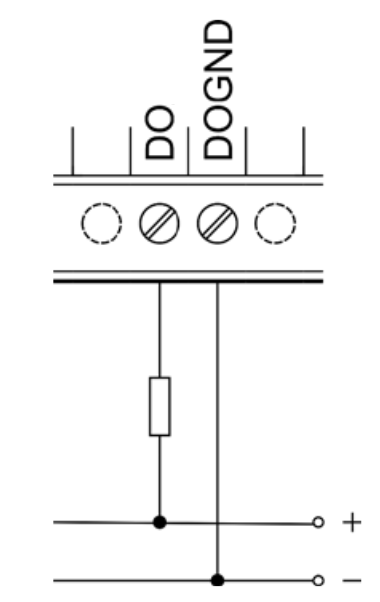
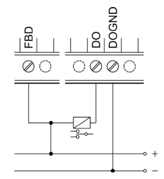
We recommend using the flyback diode available on the FBD terminal to prevent unwanted spikes when using certain loads (such as external relays) connected to digital outputs. The following picture depicts the connection of a contactor to digital output using the integrated FBD diode.
Caution!
The integrated diode is designed only for connecting devices within a single group of DO. Using the diode for other connections can cause irreversible damage to the device.
Special functions
Aside from the standard inputs and outputs, Neuron units also feature additional functions for broadening the possible applications, performance optimization and monitoring of the entire project. These functions run directly in the I/O section's microprocessor, making them independent on the control software.
PWM
PWM abbreviation stands for Pulse Width Modulation. This function serves for generating a rectangular signal of a given frequency and duty cycle on digital output and is used for digital transmission of an analog signal (such as 0-100%). PWM is typically used to regulate components powered by direct current in a way not possible with analog regulation. For example, the function can serve as an effective regulation of heating cartridges and LED lighting through an SSR relay.
Direct Switch
The DirectSwitch function can be used on any unit or extension module equipped with digital inputs and digital or relay outputs within a single section.
This function allows logical connection of digital input to digital output or relay output to automatically perform one of the available operation. DirectSwitch is independent on the control software running on unit and is suitable for control of lighting or any other time-critical applications (typically, the output response time matches the input response).
The function can be configured for one of three modes:
- Copy - input state is copied to the output
- Inverse copy - negated state of the input is set on the output
- Switch - if a rising edge is detected on the input, the output state is negated
- (Block - disables DirectSwitch)
Note:
DirectSwitch function can be configured only for the corresponding input and output, ie. only for DI_y.x input and DO_y.x (ROy.x) output, where x and y (if the y is given) numbers must match. It is not possible to use DirectSwitch simultaneously for input and output with mismatched labels, eg. DI_x.y and DO_v.z. It is also not possible to use the function for a single input and multiple outputs at the same time.
If DirectSwitch is applied to an output, it is not possible to write onto output (DO) in a regular way. Instead, you need to set the ForceOutput register to TRUE for approx. 1 second.
Default configuration
This function is used to save the current configuration of the section (extension module) into its memory. In the of power cycle of the device or reboot of the section (extension module), the stored configuration is loaded and applied. This functionality is also known as “copy
running-config to startup-config”.
| Stored data | Default configuration | Default (calculated) values |
|---|---|---|
| Output value | FALSE | |
| PWM configuration | off duty cycle: 0 resolution: 4800 | frequency: 10kHz step: 0.02% |
Master Watchdog
This function runs on the section's (extension module's) microprocessor and continuously monitor the commands from the application running on the unit. If no commands are detected within a configured time (MWD Timeout), the module's processor automatically reboots and reverts to the default configuration described above. This function ensures a safe configuration is set in case of emergency situations (unit failure, communication error or software issues) to prevent damage to controlled devices or any hazards to personnel.
Technical parameters
| Output type | SINK (NPN - open collector) |
| Output terminals | DO |
| Common ground | DOGND |
| Switching voltage | 5–50 V DC |
| Switching current continuous/pulse | 750 mA / 1 A |
| Max. total group* load | 1 A |
| Inductive load handling | Integrated FBD diode (optional) |
| Switching period (open/close) | Typ. 130 ns / 20 ns |
| Maximum PWM resolution | 16 bits |
| Maximum PWM frequency | 200 kHz |
| Galvanic isolation | No |