LED indication
This article contains the description of LED indication, all device states and a device startup simulator.
Neuron
Description of LED indicators
| Label | Function | Meaning | Colour |
|---|---|---|---|
| PWR | On | Supply voltage indication | Red |
| RUN | Blinking | Microprocessor I/O status indication | Green |
| Digital inputs (DI) | On | Indication of log.1 at the input | Green |
| Digital outputs (DO) | On | Output switch indication | Green |
| Realy outputs (RO) | On | Relay switch indication | Green |
| TX (RS485) | On | Indication of serial line broadcasting | Green |
| RX (RS485) | On | Indication of serial line receiving | Green |
| User LEDs | Selectable | Freely programmable user LEDs | Green |
| ETH | On Off Blinking Off | Connection established Connection not established Communication in progress Connection not established | Yellow Green |
The following chapters describe all LED states for the Unipi Neuron unit:
- Normal startup
- Standard functions - communication via serial lines, DirectSwitch, MasterWatchDog
- FW update on I/O boards
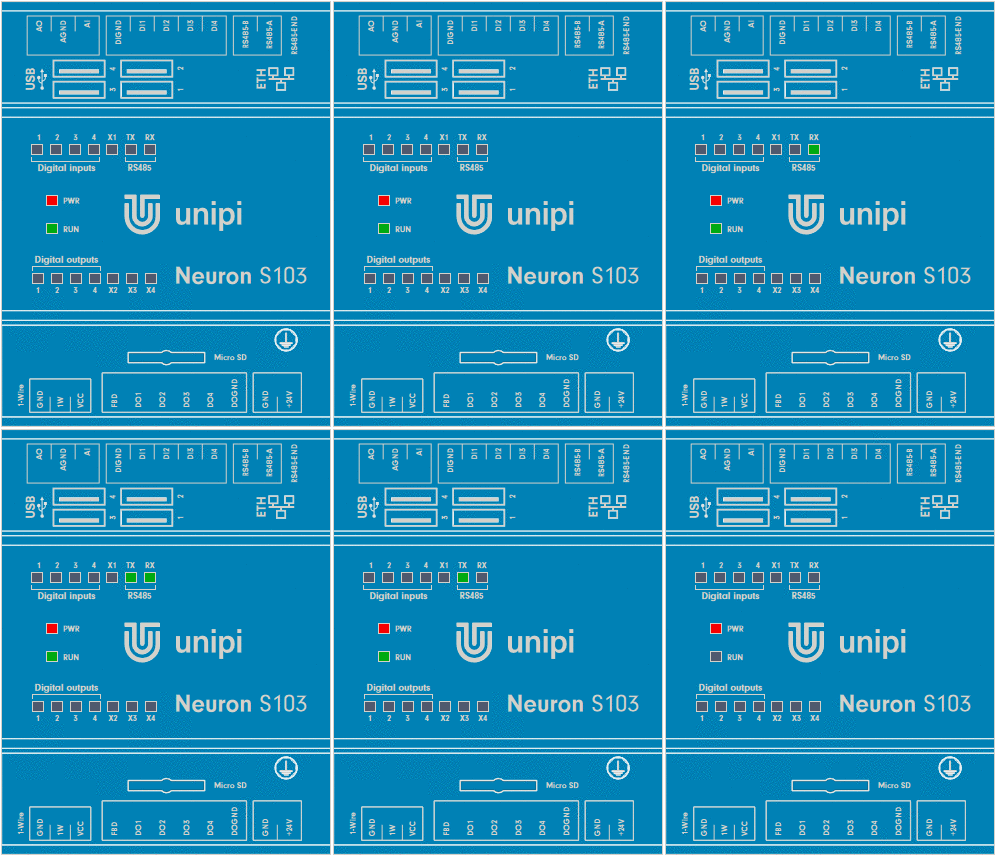
Next to the state description is a picture showing the status of LED indicators.
Some states can have several meanings and can mean e.g., a computer module error, defective SD card or an inappropriately chosen method of communication. You will find everything in the description of individual states.
Description of the individual device states
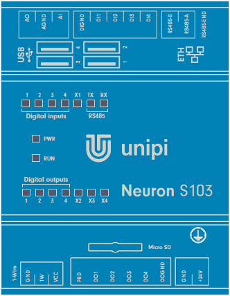
All LEDs are off
State:
Power-Off
The unit power supply is unplugged. If the PWR LED does not change its state on the unit even after connecting the power supply, try another power supply. If the state does not change after replacing the power supply, it is likely that the unit has been damaged. In this case, please contact technical support.
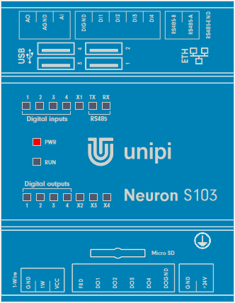
PWR is On
State:
Power-On
The unit is powered. If the unit remains in this state longer than a minute without change, it is possible that it is damage. In this case, please contact technical support.
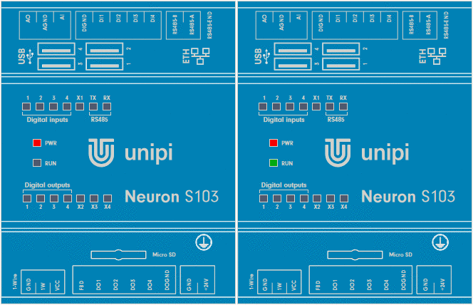
PWR is On and RUN blink slowly
State:
Does not communicate with I/O
RUN LED:
ON: 2000ms / OFF: 2000ms
If communication with I/O is not required and the web page of the unit can be displayed, or the device responds to the response test (ping), this is a regular operating state.
By default, this state is indicated when the program in the unit is not communicating with the I/O board. The state, for M and L units, is indicated for each section separately by means of a RUN LED with the corresponding marking (RUN1, RUN2, RUN3).
Because the default program in the unit does not communicate with I/O, it is also the default state when starting the device after inserting an SD card with a newly flashed OS.
If this state is indicated, the LEDs on the ETH connector are not emitting or blinking, and/or the unit cannot be found in the network, there may be a fault in the SD card. Try replacing the SD card with the newly flashed OS. If this doesn't help either, please contact technical support.
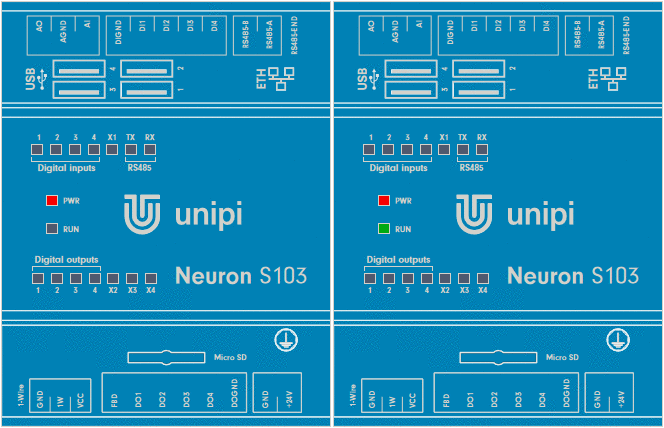
PWR is On, RUN is On with short blinks
State:
Communicates with I/O
RUN LED:
ON: 2000ms / OFF: 50ms
The main computing module (Raspberry Pi) communicates with the input and output (I/O) board of the given section. Communication can take place via Modbus TCP server, SysFS method, file entry or using API EVOK.
By default, this status is indicated when a program in the unit is running and communicating with the I/O section.
PWR is On, RUN is On with short blinks, TX and RX are blinking
Description of special states of the unit
DirectSwitch function
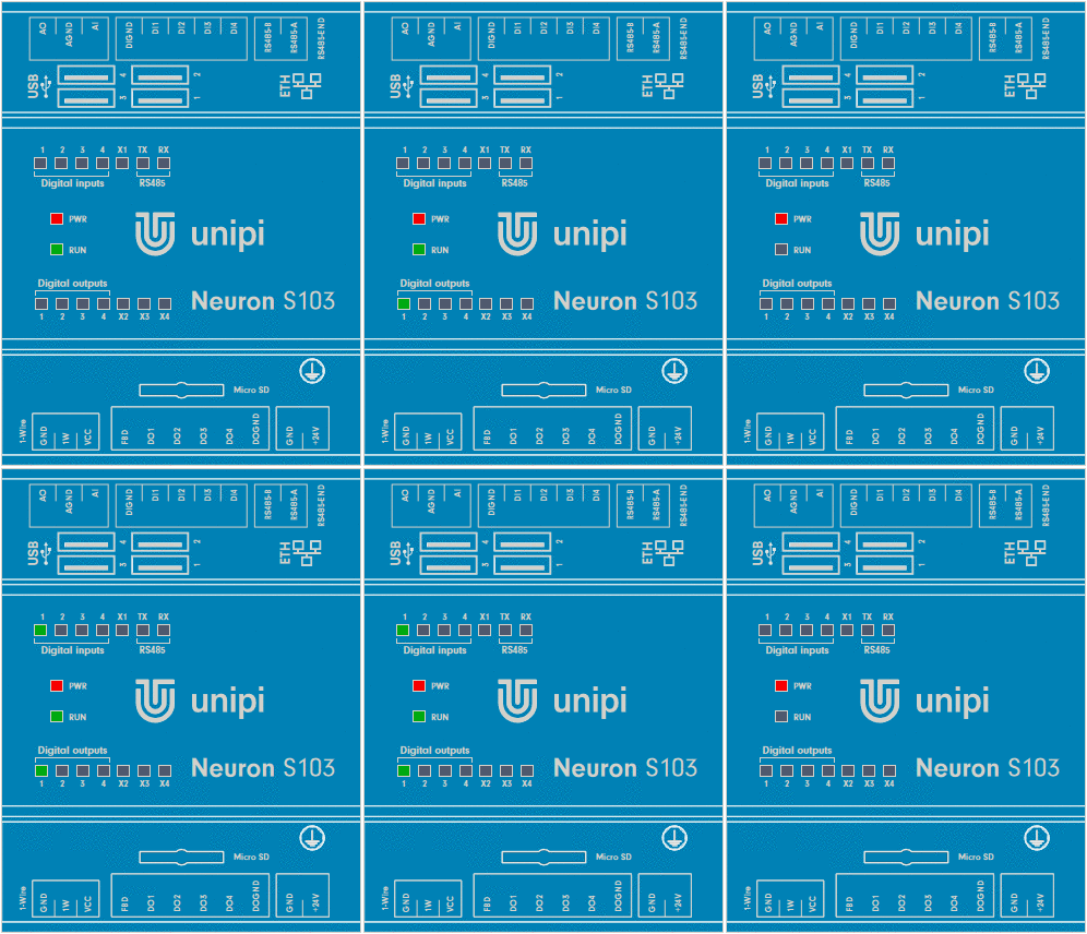
The DirectSwitch function is implemented directly in the microprocessor of the I/O section and is therefore independent of the control SW i.e., also of communication with inputs and outputs. You can read more about this function in the article about description of inputs and outputs. The function can be configured in one of three modes, their short description and illustrative LED indication can be found below:
DirectSwitch Copy
DirectSwitch Inverse-copy
DirectSwitch Toggle
Master Watchdog
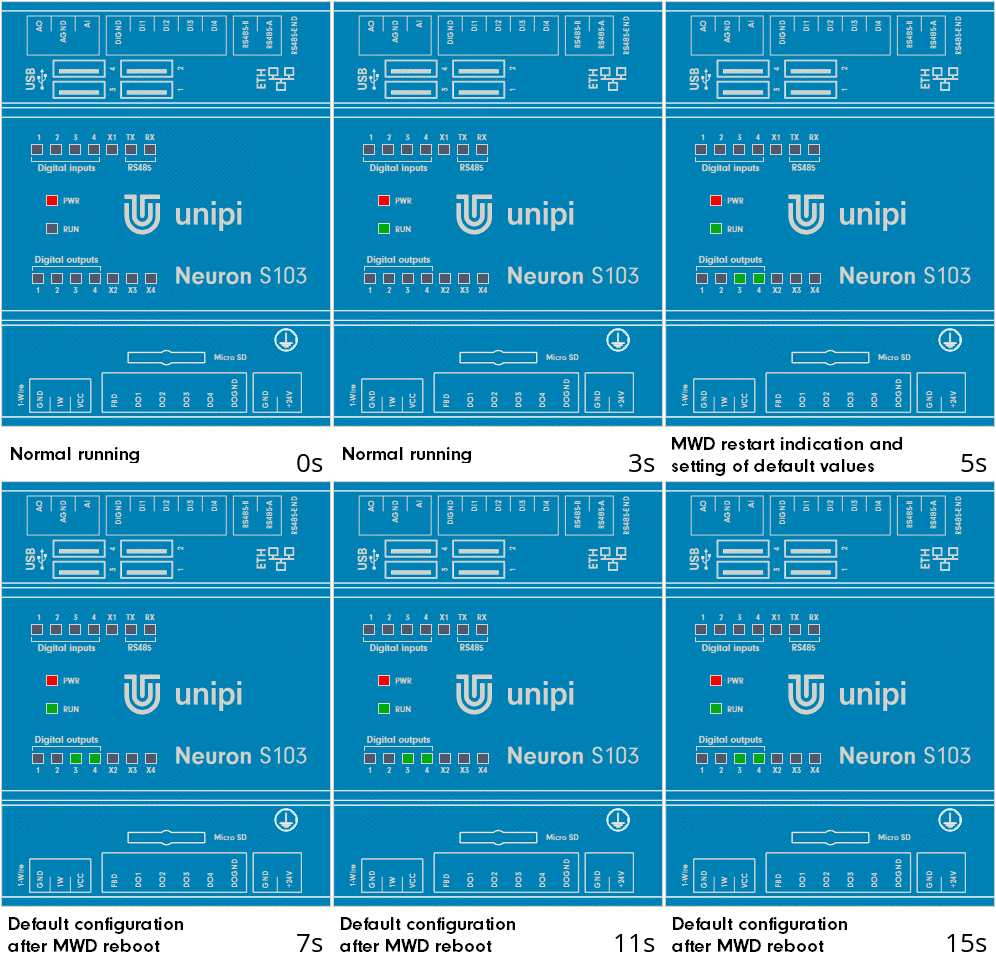
If the function is enabled on the microprocessor of the given section, the processor continuously monitors the communication from the computing module. If no commands are detected during the set time, the section processor automatically restarts and sets the saved default configuration. You can read more about this function in the article about description of inputs and outputs.
I/O board firmware update
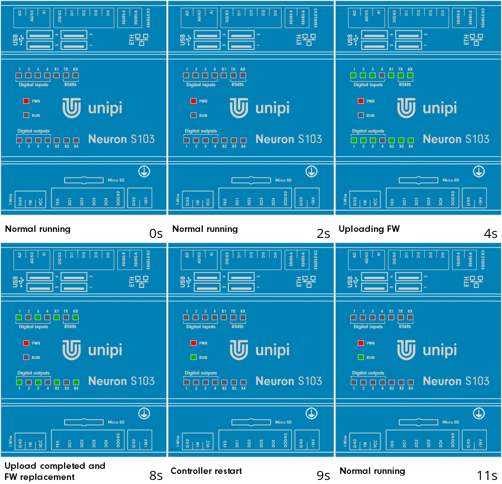
When flashing FW I/O board, all LEDs in the top and bottom row are On, except for every fourth. LEDs that are not fitted are also included in this rule.
Completion of the update is indicated by turning On every second LED and subsequent restart of the I/O section is indicated by turning On all LEDs, including RUN.
Unit startup simulator
Below we provide a unit startup simulator, where you can see the entire process from plugging in power to startup. The simulation can be started by pressing the “Plug in power” button below the unit image.
Observe the RUN LED during startup. After plugging in the power supply, the OS bootloader “uboot” starts first, this state is indicated by the first longer turn On of the diode. After a while, the OS will start.
Startup without I/O communication:
The unit is ready if the RUN LED blinks constantly slowly.
| Behaviour description | Meaning | Off | On | |
|---|---|---|---|---|
| PWR is on, RUN is on with short blinks | OS is running but not communicating with I/O board | 2000ms | 2000ms |
Startup with the program, including communication with I/O:
The unit is ready if the RUN LED is continuously On with short blinks.
| Behaviour description | Meaning | Off | On | |
|---|---|---|---|---|
| PWR is on, RUN is on with short blinks | OS is running a communnicating with I/O board | 50ms | 2000ms |
