This is an old revision of the document!
LED indication
This article contains the description of LED indication, all device states and a device startup simulator.
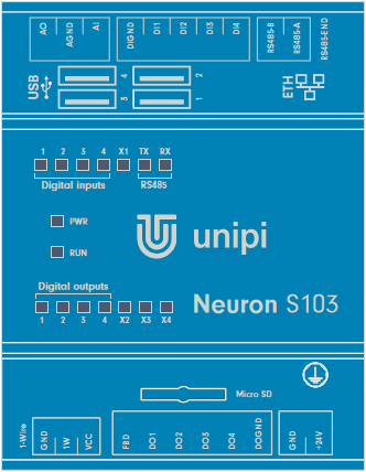
Neuron
Description of LED indicators
| Label | Function | Meaning | Colour |
|---|---|---|---|
| PWR | On | Supply voltage indication | Red |
| RUN | Blinking | Microprocessor I/O status indication | Green |
| Digital inputs (DI) | On | Indication of log.1 at the input | Green |
| Digital outputs (DO) | On | Output switch indication | Green |
| Realy outputs (RO) | On | Relay switch indication | Green |
| TX (RS485) | On | Indication of serial line broadcasting | Green |
| RX (RS485) | On | Indication of serial line receiving | Green |
| User LEDs | Selectable | Freely programmable user LEDs | Green |
| ETH | On Off Blinking Off | Connection established Connection not established Communication in progress Connection not established | Yellow Green |
The following chapters describe all LED states for the Unipi Neuron controller:
- Normal startup
- Standard functions - communication via serial lines, DirectSwitch, MasterWatchDog
- FW update on I/O boards
Next to the state description is a picture showing the status of LED indicators.
Some states can have several meanings and can mean e.g., a computer module error, defective SD card or an inappropriately chosen method of communication. You will find everything in the description of individual states.
Description of the individual device states
All LEDs are off
State:
Power-Off
The controller power supply is unplugged. If the PWR LED does not change its state on the controller even after connecting the power supply, try another power supply. If the state does not change after replacing the power supply, it is likely that the controller has been damaged. In this case, please contact technical support.
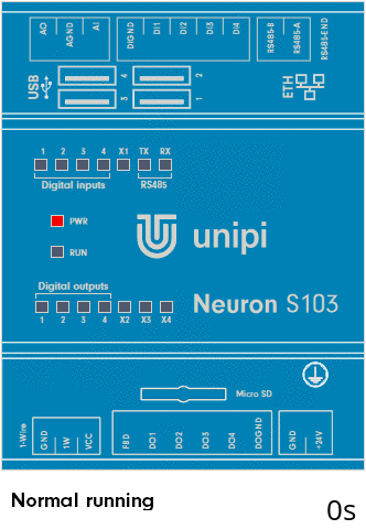
PWR is On
State:
Power-On
The controller is powered. If the controller remains in this state longer than a minute without change, it is possible that it is damage. In this case, please contact technical support.

PWR is On and RUN blink slowly
State:
Does not communicate with I/O
RUN LED:
ON: 2000ms / OFF: 2000ms
If communication with I/O is not required and the web page of the controller can be displayed, or the device responds to the response test (ping), this is a regular operating state.
By default, this state is indicated when the program in the controller is not communicating with the I/O board. The state, for M and L controllers, is indicated for each section separately by means of a RUN LED with the corresponding marking (RUN1, RUN2, RUN3).
Because the default program in the controller does not communicate with I/O, it is also the default state when starting the device after inserting an SD card with a newly flashed OS.
V případě, že je indikován tento stav, LED u ETH konektoru nesvítí, ani neblikají, a/nebo není možné kontrolér vyhledat v síti, může se jednat o vadu SD karty. Vyzkoušejte vyměnit SD kartu s nově nahraným OS. Pokud ani tento postup nepomůže, kontaktujte technickou podporu.


Svítí PWR, RUN svítí a krátce pohasíná
Stav:
Komunikuje s I/O
RUN LED:
ON: 2000ms / OFF: 50ms
Hlavní výpočetní modul (Raspberry Pi) komunikuje s deskou vstupů a výstupů (I/O) dané sekce. Komunikace může probíhat přes Modbus TCP server, SysFS metodou zápisem do souboru, nebo pomocí API EVOK.
Standardně je tento stav indikován, když program v kontroléru běží a komunikuje s I/O sekce.

Svítí PWR, RUN svítí a krátce pohasíná, TX a RX blikají
Stav:
Provoz na RS485
TX/RX LED:
náhodně blikají
Program v kontroléru komunikuje po sériové lince RS485.

Popis speciálních stavů kontroléru
DirectSwitch funkce
Funkce DirectSwitch je implementována přímo v mikro-procesoru sekce I/O a je proto nezávislá na řídícím SW, tedy i na komunikaci se vstupy a výstupy. Více o této funkci se dočtete v článku věnovaném popisu vstupů a výstupů. Funkci lze nakonfigurovat do jednoho ze tří režimů, jejich krátký popis a názornou indikaci LED naleznete níže:
DirectSwitch Copy
Stav vstupu je zapsán na výstup.

DirectSwitch Inverse-copy
Negovaný stav vstupu je zapsán na výstup.

DirectSwitch Toggle
Pokud je na vstupu detekována náběžná hrana, stav výstupu je negován.

Master Watchdog
Pokud je funkce na mikro-procesoru dané sekce povolena, procesor nepřetržitě monitoruje komunikaci z výpočetního modulu. Pokud během nastaveného času nejsou detekovány žádné příkazy, procesor sekce se automaticky restartuje a nastaví uloženou výchozí konfiguraci. Více o této funkci se dočtete v článku věnovaném popisu vstupů a výstupů.

Aktualizace firmwaru desky I/O
Při přehrávání FW desky I/O svítí, všechny LED v horní i dolní řadě, kromě každé čtvrté. Do tohoto pravidla se zahrnují i LED, které nejsou osazeny.
Dokončení aktualizace je indikováno rozsvícením každé druhé LED a následný restart sekce I/O je indikován rozsvícením všech LED, včetně RUN LED.
Simulátor spuštění kontroléru
Níže poskytujeme simulátor spuštění kontroléru, kde lze vidět celý průběh od připojení napájení až po spuštění. Simulaci lze spustit tlačítkem “Připojit napájení” pod obrázkem kontroléru.
Při spuštění kontroléru sledujte diodu RUN. Po připojení napájení nejprve startuje zavaděč OS “uboot”, tento stav je signalizován prvním delším rozsvícením diody. Po chvíli začne startovat OS.
Spuštění bez komunikace s I/O:
Kontrolér je připraven, pokud dioda RUN trvale pomalu bliká.
| Popis chování | Význam | Nesvítí | Svítí | |
|---|---|---|---|---|
| Svítí PWR, RUN svítí a krátce pohasíná | OS běží, ale nekomunikuje s deskou I/O | 2000ms | 2000ms |
Spuštění s programem včetně komunikace s I/O:
Kontrolér je připraven, pokud dioda RUN trvale svítí a opakovaně na krátkou dobu pohasíná.
| Popis chování | Význam | Nesvítí | Svítí | |
|---|---|---|---|---|
| Svítí PWR, RUN svítí a krátce pohasíná | OS běží a komunikuje s deskou I/O | 50ms | 2000ms |