This is an old revision of the document!
Relay outputs are terminated to ROy.x and COM and serve for switching two-state devices via either alternating or direct voltage. The COM terminal is usually shared by two relays and is switched to ROy.x terminal. Relays are connected in NO states, eg. by default the contacts are disengaged.
Switching of each really is indicated by a LED with a corresponding label. Overload and overvoltage protection is provided externally by a circuit breaker (ideally one for each output or entire I/O group). Nominal current and circuit breaker type should be selected according to the load and its characteristics concerning the maximum current on the output or output group.
Note:
If an induction load is connected (eg. electric motors, relay coils, contactors or power cables in extensive electric installations), we recommend protecting the relay outputs by a corresponding external element (eg. varistor, RC circuit or a suitable diode).
If a capacitive load is connected (eg. LED lighting power sources), we recommend protecting relay contacts against inrush current by connecting a corresponding thermistor to the relay's output.
Connection
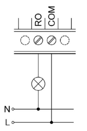
The following image illustrates the connection of an ohmic (resistance) load with alternating voltage to a relay output: