DIP switch settings:
An external power supply can be used to power digital inputs. This setup is available through a correct setting of DIP switches A and B. Using external power supply includes galvanic isolation of digital inputs. The Unipi 1.1 Lite board must be unplugged from power during the DIP switch configuration. After finishing the setup and connecting the negative pole of the external supply (see below), you can plug in the board's power source.
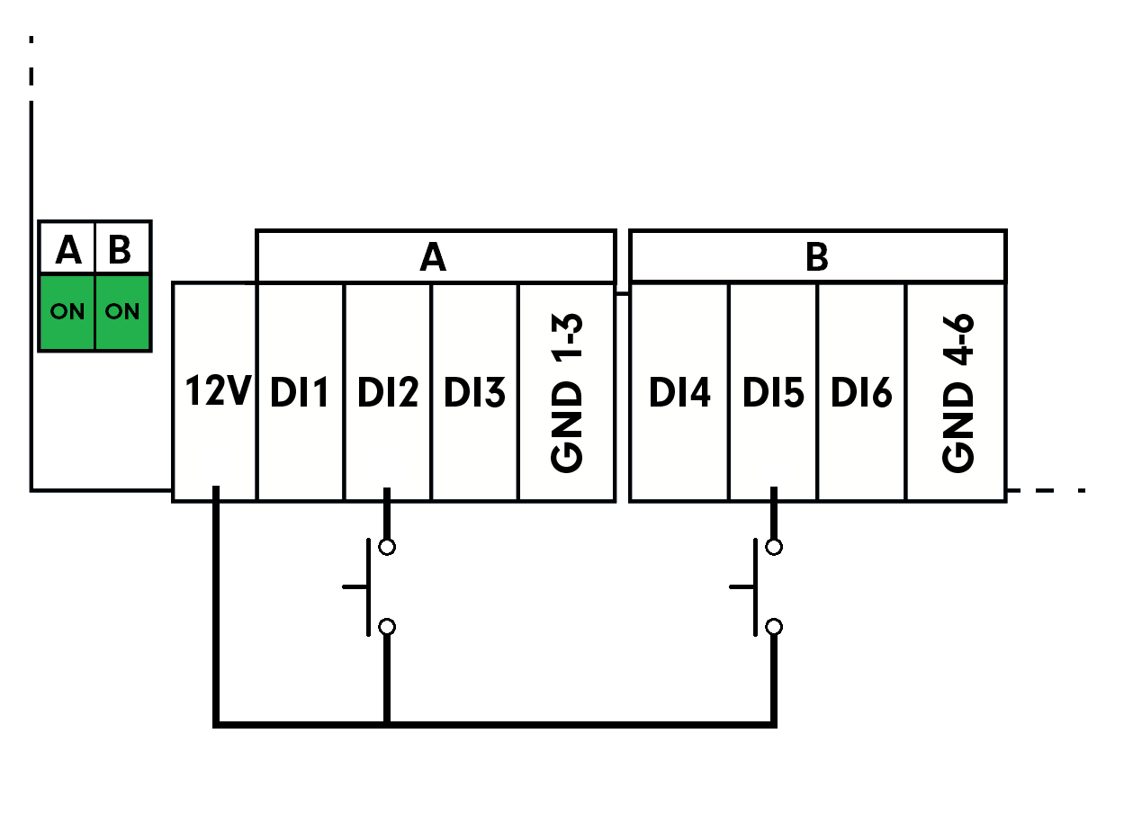
By default, the DIP switches A and B are set to ON. Digital inputs are connected to a 12 V⎓ internal power supply:
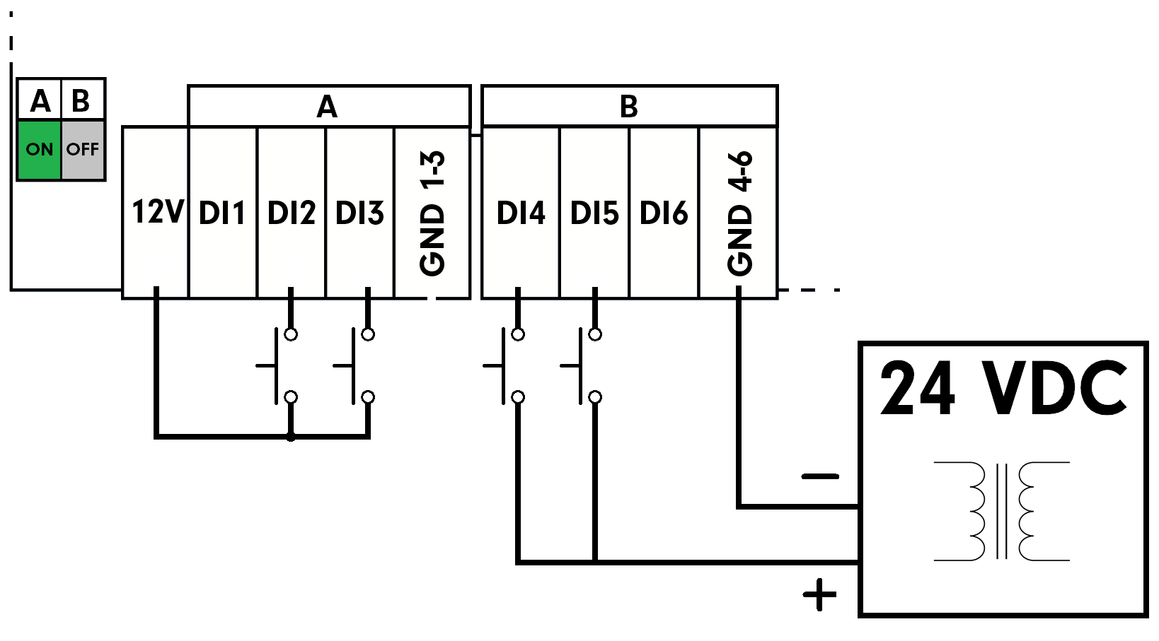
DIP switch A is set to OFF, DIP switch B is set to ON. Digital inputs of the A group (ie. DI1 to DI3) are now ready for connection of an external power supply. Group B inputs are still powered by the 12 V⎓ internal supply.

This is possible also in reverse → DIP switch A is set to ON, DIP switch B is set to OFF. Digital inputs of the A group are now powered by the internal 12 V⎓ source, group B inputs are ready for connection of an external power supply.
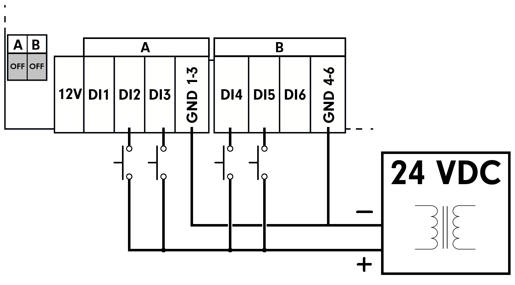
If both DIP switches A and B are set to OFF, digital inputs of both A and B groups (DI1 to DI6) are ready for connection of an external power supply: