This is an old revision of the document!
Unipi Extensions
Looking for a guide to connect the extensions to Patron, Neuron or Axon controllers with Mervis? Please visit this detailed tutorial.

Unipi Extension is a product line of extension modules designed as a simple and affordable method of extending automation systems by additional inputs/outputs without the need to purchase more Unipi controllers. The modules communicate with the PLC using the RS485 serial line and while primarily designed for Unipi controllers, they can be used in combination with any other device featuring RS485 interface and Modbus RTU protocol support. That makes Unipi Extension modules an excellent choice in case other PLC vendors do not offer their native extensions or their purchase would be too expensive.
Main advantages of Unipi Extension modules:
- Counter on each digital input,
- DirectSwitch functionality allows an instantanenous reaction of outputs to input signals in specific conditions,
- Modules are able to store default output values,
- MasterWatchdog functionality monitors the communication between the module and the PLC and will automatically reset the module's I/Os to preconfigured default values in case of communication failure.
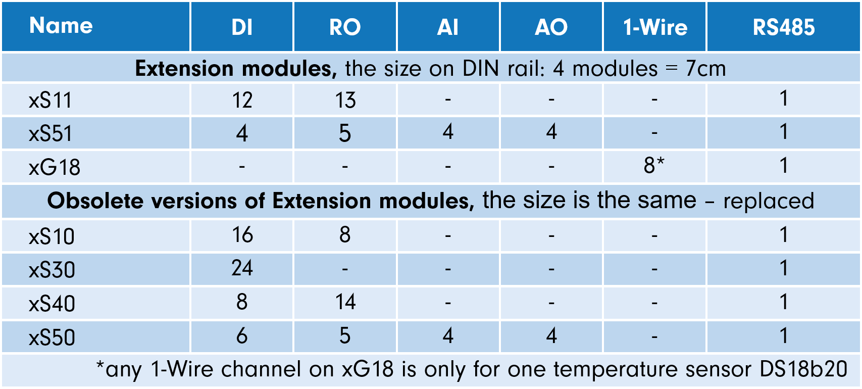
Unipi Extension model overview
The list of models is available below.
Examples of usage
Extension modules are a simple and affordable solution in case you need more I/Os than your current controller can offer. Modules do not require any individual programming as they are controlled by the control logic stored in the PLC. Multiple extension modules can be connected to a single bus, allowing you to create a large input/output network controlled by a single PLC.

Extension modules can be alternatively used as a set of inputs/outputs accessible outside the distribution box housing the PLC (another room, storey etc.). You can simply install an extension module into the remote location, connect external devices to it and then connect it to the PLC using a single RS485 cable. By doing so, you can significantly reduce the needed amount of cabling and related expenses.

Special functions
Aside from standard inputs/outputs the extension modules also feature other useful functions to enhance their performance and broaden their potential.
Counter
The counter is one of the most useful functions. It is a high-speed counter of signal rising edges running independently on the control software. Simply put, Counter can accurately register even very short pulses.
For this purpose, controllers feature register with a total size of 64 bits. In Mervis IDE prototypes Counter inputs are marked as CNT inputs.
Direct Switch
This function is able to directly connect a digital input to relay output. Direct Switch runs independently on the PLC's control logic, which makes it suitable for applications requiring short response time (ie. lighting control). The function can be configured into one of three modes:
- Copy: the output is switched by active input
- Invert: the output is switched by inactive input
- Toggle: the output is switched with each change on the input
Note: Only DI_x.y and DO_x.y / RO_x.y I/Os can be coupled by Direct Switch. The function cannot be used if the input's and output's name does not match (ie. DI_x.y and RO_v.z.).
Default settings
This function stores the module's configuration into its internal memory. If the device reboots the module will automatically switch to the stored configuration
Master Watchdog
This function continuously monitors the communication between the extension module and the controller. If no communication is detected in a time set by the user, the module's processors will automatically revert to the default configuration. This function is thus able to keep the device running in case of a controller failure, software error or other similar problems.
I/O boards of Unipi extension modules each feature their microprocessor that maintains the basic I/O functionality even in case of losing connection with the PLC or PLC failure.
Module addressing and communication parameters
Modules can be configured using blue-white (HW configuration) switches placed next to the power connectors, or alternatively next to the RS485 on some models. Another option is configuration via Modbus registers (SW configuration). Configuration via DIP switches offers enough options for most applications, while configuration via Modbus registers provides broader possibilities (wider range of addresses and bitrates).
HW configuration is recommended for the module's first use and the subsequent SW configuration upload.
SW configuration via Modbus RTU
Modules can be easily configured in Mervis, as described in this guide.
Default communication parameters (SW configuration)*:
- Number of data bits: 8 bits (fixed)
- Modbus address: 15
- Bitrate: 19200 baud
- Parity: None
*SW configuration of the module is used only when all address switches are set to 0 (OFF). Switch states are used only during the module's startup (connecting the power supply, SW reset, Master Watchdog).
Modbus registre tables for Unipi Extension:
HW configuration using DIP switches
Each Unipi Extension features a set of blue-white switches.
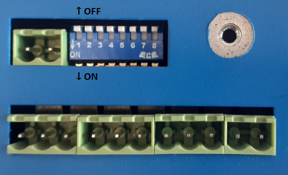
Extension xG18:
This module features 6 configurable switches located at the left bottom part. The switch no.6 is placed closest to the power connectors. The lone switch next to the RS485 connector serves to attach/detach terminal resistor, eg. cannot be used for configuration.

Switch:
- n.1 → Address bit 1 (OFF - ignored, ON - value +1)
- n.2 → Address bit 2 (OFF - ignored, ON - value +2)
- n.3 → Address bit 3 (OFF - ignored, ON - value +4)
- n.4 → Address bit 4 (OFF - ignored, ON - value +8)
- n.5 → Bitrate selection (OFF - 19200, ON - 9600)
- n.6 → Parity selection (OFF - even, ON - none)
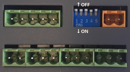
Extension xS11, xS51:
These modules have 5 switches located next to the power connector at the module's bottom. The no.5 switch is closest to the power connector.
Switch:
- n.1 → Adress bit 1 (OFF - ignored, ON - value +1)
- n.2 → Adress bit 2 (OFF - ignored, ON - value +2)
- n.3 → Adress bit 3 (OFF - ignored, ON - value +4)
- n.4 → Bitrate selection (OFF - 19200, ON - 9600)
- n.5 → Parity selection (OFF - even, ON - none)
Extension xS10, xS30, xS40:
These modules feature 8 switches located next to the RS485 connector at the upper part of the module. No. 1 switch is closest to the RS485 connector.
Switch:
- n.1 → Attaches/detaches the bus terminating resistor (not related to configuration
- n.2 → Unused
- n.3 → Address bit 1 (OFF - ignored, ON - value +1)
- n.4 → Address bit 2 (OFF - ignored, ON - value +2)
- n.5 → Address bit 3 (OFF - ignored, ON - value +4)
- n.6 → Address bit 4 (OFF - ignored, ON - value +8)
- n.7 → Bitrate selection (OFF - 19200, ON - 9600)
- n.8 → Parity selection (OFF - even, ON - none)
Extension xS50:
Only 3 switches are available on this module, located between the power connector and the digital input terminals at the module's bottom. Switch no. 3 is closest to the power connector.

Switch:
- n.1 → Address bit 1 (OFF - ignored, ON - value +1)
- n.2 → Address bit 2 (OFF - ignored, ON - value +2)
- n.3 → AAddress bit 3 (OFF - ignored, ON - value +4)