Digital inputs serve for an indication of TRUE/FALSE logic states.
Unipi 1.1
TRUE logic state (switched on) is indicated by the corresponding LED placed beyond the inputs.
Note:
For connecting external devices to digital inputs, we recommend using a different (separate) power supply in order to retain galvanic isolation.
The software detects TRUE state if the input voltage between the given DIx and DIGND terminals is in range of 7-24 V⎓. If the voltage decreases below 3 V⎓, the FALSE state is indicated. The voltage between 3-7 V⎓ is detected as a non-defined state.
Connection
Unipi 1.1 features the option to connect internal and/or external power supply for digital inputs. By default, the internal source is sufficient. However, if you need to connect an external reference ground, you can do so by using P01 and P02 terminals after properly setting jumpers JP2-JP5. Always set the jumpers first and only then connect the power supply's negative pole see the guide below. The power supply's positive pole is to be connected through the external device using the Ixx terminal, as described by the following pictures:
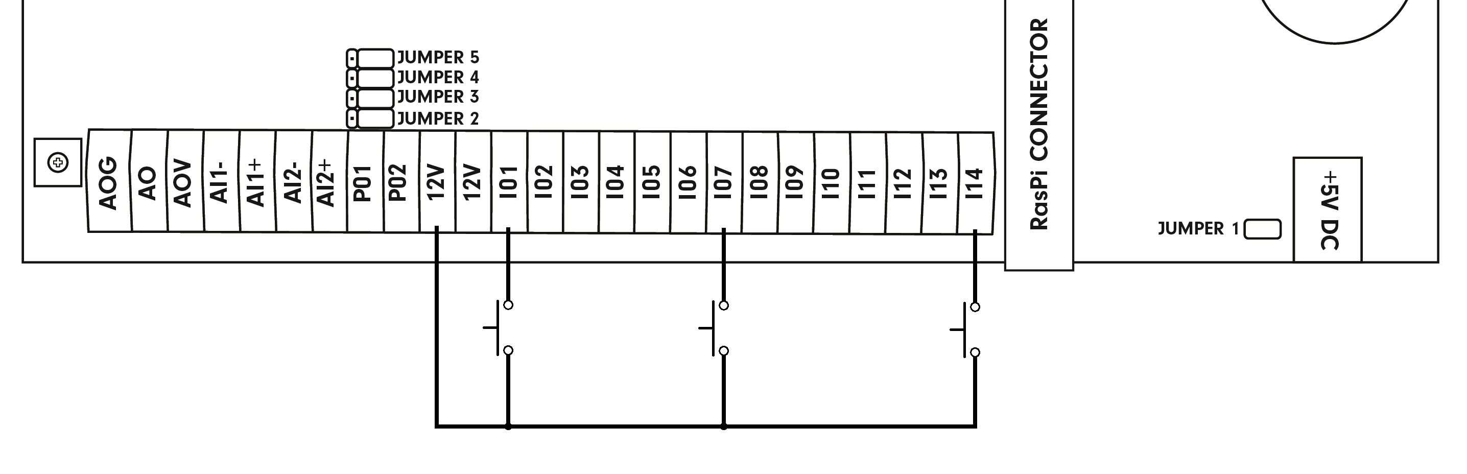
DI connection with the internal power supply:
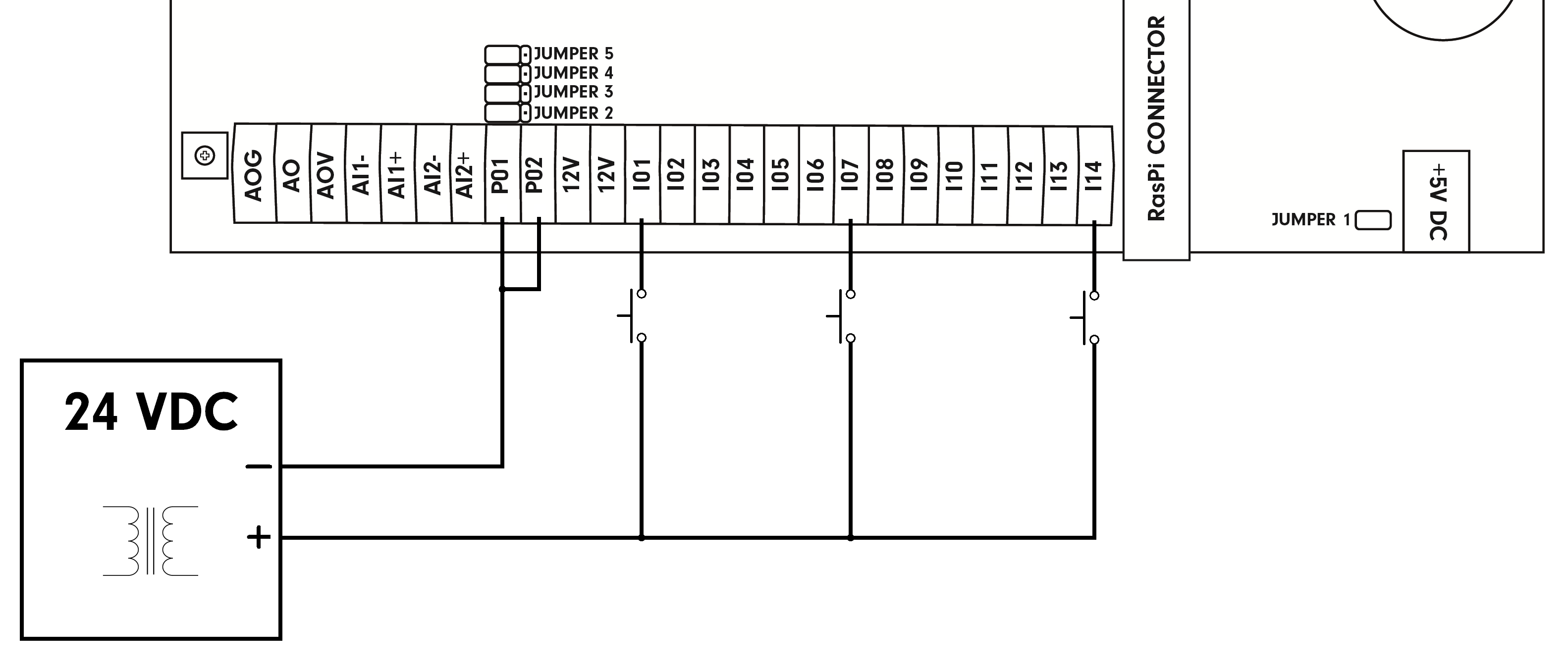
DI connection with the external power supply:
Notice the settings of jumpers JP2 - JP5.
DI connection with both the internal and external power supply:
Notice the settings of jumpers JP2 - JP5.
