This is an old revision of the document!
Digital inputs serve for an indication of TRUE/FALSE logic states and can be also used as counters to collect data from pulse meters, monitor engine revolutions etc. Another possible application is to connect input and output using the DirectSwitch function.
TRUE logic state (switched on) on input is indicated by LED with the corresponding marking matching the input label.
The software detects TRUE state if the input voltage between the given DIx and DIGND terminals is in range of 7-35 V⎓. If the voltage decreases below 3 V⎓, the FALSE state is indicated. The voltage between 3-7 V⎓ is detected as a non-defined state.
Connection
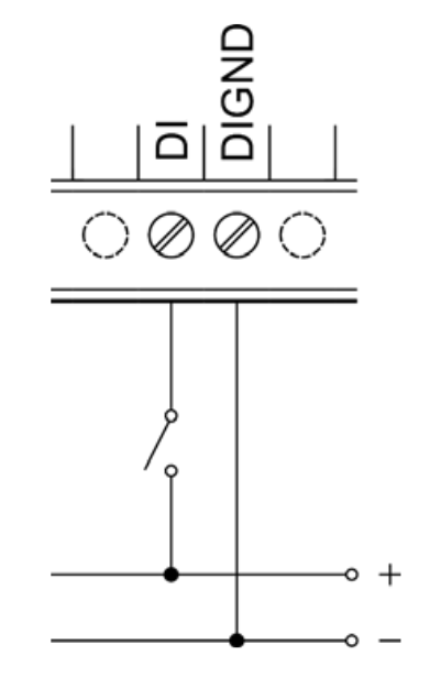
Each connector with digital inputs features a common DIGND terminal for connection of DC power source negative pole. The positive pole of the power supply is to be connected to the DIx or DIy.x terminal through the connected external device. See the following image for illustration:
Note:
For connection of external devices to digital inputs, we recommend using a different (separate) power supply from the one used to power the device (unit/Extension) in order to retain galvanic isolation. Each digital input group also feature a DIGND terminal added specifically for connection of the separate power supply negative pole.


