Measuring mode is set depending on the used software. The negative pole of the measured external device is connected to AGND terminal of the connector used, its positive pole (signal) is then connected to AIx or AIy.x terminal).
Note:
In its factory settings, the device is set to voltage measurement to prevent any potential damage of connected devices or sensors in case an unsuitable device/sensor is connected.
Caution!
Before connecting the measuring device, it is necessary to check measurement settings using the chosen software and according to the type of the connected device - see the measurement description below.
Connection
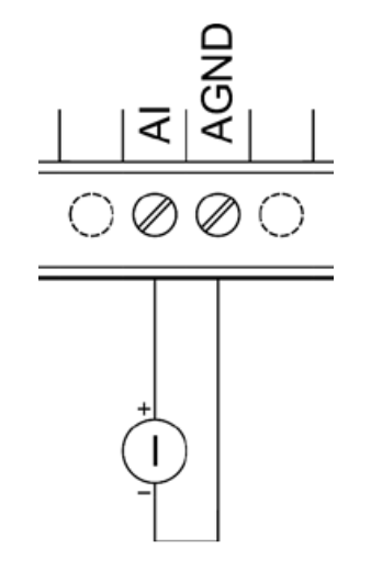
The following images illustrate the setup for measuring a voltage and current source on AI and AGND terminals.
Voltage measurement

Current measurement
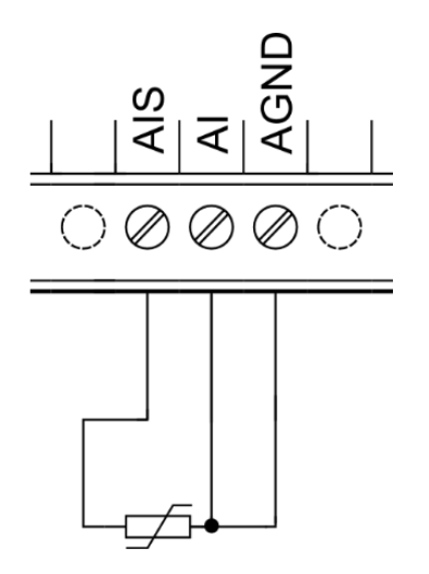
Resistance sensors can be connected to analog inputs using a two-wire or three-wire method. The three-wire method holds the advantage of preventing measuring errors caused by the resistance of the used wire.
Two-wire method
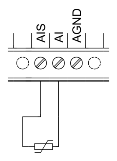
Three-wire method
Mode description
Analog inputs on Extension modules can perform accurate measurements of current, voltage or resistance. Measurement mode needs to be set first in the control software. In voltage and resistance mode you can choose from two accuracy modes. The measured value is of real type and corresponds with the measured input value (V⎓, mA, Ω).
This type of analog input supports the following modes:
- 0–10 V⎓ voltage
- 0–2.5 V⎓ voltage
- 0–20 mA current
- 0–1960 Ω resistance (three-wire)
- 0–100 kΩ resistance (two-wire)